
Manual

3
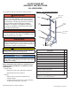
Figure 6 - Cross Member Assembly
Slide Tab of Cross
Member Into Slot
in Upright
Slide Tab of Cross
Member Down
to Engage with
Upright
Left Upright
Cross Member
Bolt Location
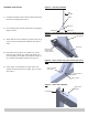
Figure 7 - Cross Member Locations
Left side
Assembly
Right side
Assembly
Center Cross
Member Location
50-100
Center Cross
Member Location
150-299
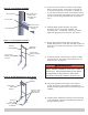
Figure 8 - Boiler Wall Bracket to Floor Stand
Upper Cross
Member
Boiler Wall
Mount
Bracket
Secure To
Floor With
Proper Lag/Bolt
4 Locations
Secure To Floor
With 3/8" Lag/
Bolt locations
6.
Insert Lower Cross Member into tabs of Left upright.
Note 2 locations of tabs. Center tabs on uprights are
for 50-100 model boilers. Lower tabs on uprights are
for 150-299 model boilers. Slide Cross Member down to
engage Cross Member with Upright. Screw in place with
1/4-20 x 5/8 Hex Flange Bolts and Nuts. See Figure 6
and 7.
7.
Assemble Right Upright Assembly using same
procedure used for left upright assembly. Use
remaining parts - 2 Base Feet, 1 Base Leg, 1 Brace,
Right side Upright and bolts and nuts. See Figure 7.
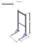
8.
Engage Right Side Assembly with Cross Members
already assembled on to Left Side Assembly. Tighten all
bolts and nuts in oor stand assembly (13 pair of bolts
and nuts).
9.
Install wall bracket received with your Boiler to Upper
Cross Member of oor stand using supplied 5/16-18
bolts and nuts. See Figure 8.
WARNING
Fire, explosion, asphyxiation and electrical shock
hazard. Improper installation could result in death or
serious injury. Securely fasten stand to oor before
mounting boiler to stand. Failure to follow these
instructions could result in death or serious injury.
!
10.
Use proper lag/bolts (not included) to secure Stand
to oor. See Figure 8. It is installer's responsibility to
determine proper lag/bolts based on actual oor type and
condition.
11.
Complete Boiler installation following instructions found
in the Installation, Operation and Maintenance Manual
provided with your boiler.