Models DKVLT-050 DKVLT-075 DKVLT-100 DKVLT-150 DKVLT-200 DKVLT-299 WALL MOUNTED GAS BOILER INSTALLATION, OPERATION & MAINTENANCE MANUAL 050/075/100/150/200 SIZE SHOWN Manufactured by: ECR International, Inc. 2201 Dwyer Avenue, Utica NY 13501 web site: www.ecrinternational.com An ISO 9001-2008 Certified Company P/N# 240008888, Rev.
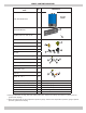
VERIFY CONTENTS RECEIVED Description Item No. Fully Assembled Boiler 1 Metal Wall Bracket 2 Lag Bolt, 3/8" x 3" Hex (4 ea) 3 *Safety Relief Valve 4 3/4" Tee 5 3/4" Nipple 6 3/4" x 1/4" Elbow 7 Illustration 299 SIZE SHOWN 2 3 4 8 5 7 6 Air Vent 8 **Temperature Pressure Gauge 9 Bushing 3/4" x 1/4" 10 3/4" Tee (Same as No. 11) 11 Nipple 1¼ x 5½ 12 Drain Valve, 3/4" 13 3/4" Tee 14 Nipple 1¼ x 5½ 15 Bushing 7/8" OD, Heyco (2 ea) 16 Used for electrical wire knockouts.
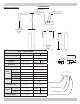
DIMENSIONS DIMENSIONS FIGURE 1-1 Dimensions Safety Relief Valve Connection (¾ NPT) (D) Vent Connector Combustion Air (E) Wall Hanging Bracket (D) (A) (B) Table 1 : Physical Data Models 050/075/100 Width (A) 20" (508mm) 23" (584mm) Height (B) 30" (762mm) 40" (1041mm) Depth (C) 14" (356mm) Bracket (D) 28" (711mm) 40" (1016mm) Height (E) 31" (787mm) 42" (1092mm) 1-1/4" NPT 1-1/4" NPT 2" (51mm) 2" (51mm) 5" (127mm) 2" (51mm) Location (I) 3" (76mm) 4-½" (114mm) Location (J) 4-
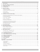
TABLE OF CONTENTS 1 - Introduction ������������������������������������������������������������������������������������������������������������������������������� 5 2 - Important Safety Information ���������������������������������������������������������������������������������������������������� 6 3 - Component Listing ��������������������������������������������������������������������������������������������������������������������� 7 4 - Locating Boiler �������������������������������������������������
1 - INTRODUCTION 1.1 Designated Use • Hot water heating boiler. • Indoor installation. • Closet or alcove installation. • Direct vent boiler. • For use with natural gas or liquefied petroleum gases (LP/propane). 1.2 The unit MUST NOT: • Directly heat potable water. Indirect heating is acceptable. • Heat water with non-hydronic heating system chemicals present (example, swimming pool water). • Exceed 150 psig (1.03 MPa) maximum allowable working pressure. • Exceed 195°F (90.5°C) system design temperature. 1.
2 - IMPORTANT SAFETY INFORMATION 2.1 General Boiler installation shall be completed by qualified agency. See glossary for additional information. 2.3 Installation shall conform to requirements of authority having jurisdiction or in absence of such requirements: • National Fuel Gas Code, ANSI Z223.1/NFPA 54. ! WARNING • National Electrical Code, NFPA 70. Fire, explosion, asphyxiation and electrical shock hazard. Improper installation could result in death or serious injury.
3 - COMPONENT LISTING 3.1 Component Listing - Refer to diagrams on 20. Gas (Control) Valve Delivers proper quantity of fuel 1. User Interface Displays information regarding boiler 21. Supply Water Temperature Sensor and High Limit following pages. to Combustion Air Blower. See section 7. Switch condition. Allows adjustment of boiler operating parameters. NOTE: Does not replace thermostat used to control central heating space. 22. Low Water Cutoff Senses inadequate quantity of water.
3 - COMPONENT LISTING FIGURE 3-1 Boiler Components (Viewed from Back of Boiler) AIR VENT SAFETY RELIEF VALVE VENT CONNECTOR NOTE: See Section 5-3 For Safety Relief Valve Piping Instructions COMBUSTION AIR INLET WALL MOUNT SUPPORT BRACKET FIGURE 3-2 Lower Jacket (Viewed from front of boiler) Lower Jacket Connector to User Interface FIGURE 3-3 Upper and Lower Jacket Latch (Viewed from front of boiler) Disconnect connector before removing lower jacket Upper and Lower Jacket Latch (1) User Interface S
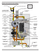
3 - COMPONENT LISTING FIGURE 3-4 Boiler Components 50/75/100 MBH (View from Front of Boiler) As seen on front cover (28) AIR VENT (23) SAFETY RELIEF VALVE NOTE: See Section 5 For Piping Instructions (25) VENT CONNECTOR (21) SUPPLY WATER TEMPERATURE SENSOR & HIGH LIMIT SWITCH (2) COMBUSTION AIR INLET (22) LOW WATER CUTOFF (13) INTERNAL PRIMARY LOOP BALL VALVE (5) IGNITER (20) GAS (CONTROL) VALVE (6) FLAME SENSOR (19) COMBUSTION AIR BLOWER (7) SIGHT GLASS (32) FLUE AIR MIXTURE PRESSURE TEST PORT (
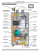
3 - COMPONENT LISTING FIGURE 3-5 Boiler Components 299 MBH (View from Front of Boiler) (28) AIR VENT (23) SAFETY RELIEF VALVE NOTE: See Section 5 For Piping Instructions (25) VENT CONNECTOR (2) COMBUSTION AIR INLET (21) SUPPLY WATER TEMPERATURE SENSOR & HIGH LIMIT SWITCH (19) BLOWER VENTURI (22) LOW WATER CUTOFF (6) FLAME SENSOR (33) COMBUSTION ANALYSIS TEST PORT (7) SIGHT GLASS & (5) IGNITER (34) INTERNAL PUMP RELAY (29) BOILER CONTROL MODULE Fuse and Holder (31) TRANSFORMER (9) HEAT EXCHANGER
4 - LOCATING BOILER FIGURE 4-1 Clearance to Combustible Materials 4.1 Boiler Location Considerations • Ambient room temperature always above 32°F (0°C) to prevent freezing of liquid condensate. • Approved for installation in closets. • Protect gas ignition system components from water (dripping, spraying, rain, etc.) during operation and service (circulator replacement, condensate trap, control replacement, etc.). A A B C F F • Wall mount only.
4 - LOCATING BOILER 4.2 Pre-pipe supply and return water connections FIGURE 4-2 Wall Mount Bracket Engaged with Bracket on Boiler with factory fittings before wall mounting. Center brackets. Avoid overhang on sides of wall mount bracket. 4.3 Wall Mounting Mount boiler on wall using wall mounting bracket included with unit. • Structure must be capable of supporting boiler weight plus 60 lbs (28 kg). See Table 1, page 2.
5 - HYDRONIC PIPING ! WARNING 5.1 General • Install piping in accordance with authority having jurisdiction. • Poison hazard. Ethylene glycol is toxic. Do not use ethylene glycol. NOTICE Use two (2) wrenches when tightening and fitting to pipe boiler's threaded fittings. Boiler's internal piping can be damaged if subjected to excessive torque. • Never use automotive or standard glycol antifreeze, even ethylene glycol made for hydronic systems.
5 - HYDRONIC PIPING ! WARNING • Install discharge piping from safety relief valve. See figure 5-2. Burn and scald hazard. Safety relief valve could discharge steam or hot water during operation. Install discharge piping per these instructions. • Use ¾" or larger pipe. • Use pipe suitable for temperatures of 375°F (191°C) or greater. FIGURE 5-2 Safety Relief Valve Discharge Piping • Individual boiler discharge piping shall be independent of other discharge piping.
5 - HYDRONIC PIPING Piping Legend NOTICE Illustrations are meant to show system piping concept only. Installer responsible for all equipment and detailing required by authority having jurisdiction.
5 - HYDRONIC PIPING FIGURE 5-5 Single Boiler Two-Pipe Zoned System With Zone Valves DHW Pump CH/System Pump Heat exchanger ball valve open (as shipped) 3/8"/10mm Open End Wrench may be required to turn valve FIGURE 5-6 Single Boiler Two-Pipe Zoned System With Zone Pumps DHW Pump Heat exchanger ball valve open (as shipped) Zone Pump 3/8"/10mm Open End Wrench may be required to turn valve 16
5 - HYDRONIC PIPING FIGURE 5-7A Single Boiler Using Primary/Secondary Pumping With Closed External Primary Loop Heating Load Heating Load 12"(305mm) Maximum separation Heating Load 12"(305mm) Maximum separation Existing closely spaced tees in primary system loop Limit length to 5' (1.6m) CH/System Pump Heating system with existing primary loop.
5 - HYDRONIC PIPING FIGURE 5-8A Multiple Boiler Two Pipe Zoned System With Zone Valves - (See Multiple Boiler Guide) DHW Pump CH/System Pump 12"/305mm Maximum Separation System Temperature Sensor Size common piping per maximum heat capacity of entire system Limit length to 5' (1.
5 - HYDRONIC PIPING FIGURE 5-8B Multiple Boilers Using Primary/Secondary Pumping with Closed External Primary Loop Heating Load Heating Load 12"/305mm Maximum Separation Existing closely spaced tees in primary system loop 12"/305mm Maximum Separation CH/System Pump System Temperature Sensor Heating Load Size common piping per maximum heat capacity of entire system Limit length to 5' (1.
5 - HYDRONIC PIPING 5-8C Multiple Boilers Using Primary/Secondary Pumping with Open External Primary Loop 12"/305mm Maximum Separation Existing closely spaced tees in primary system loop 12"/305mm Maximum Separation CH/System Pump System Temperature Sensor Size common piping per maximum heat capacity of entire system Limit length to 5' (1.
6 - COMBUSTION AIR AND VENT PIPING 6.1 General Fuel Code, ANSI Z223.1/NFPA 54 and/or Natural Gas and Propane Installation Code, CAN/CSA B149.1. When re-sizing any portion of common venting system, common venting system should be re-sized to approach minimum size as determined using appropriate tables in Chapter 13 of the National Fuel Gas Code, ANSI Z223.1/ NFPA 54 and/or Natural Gas and Propane Installation Code, CAN/CSA B149.1. This boiler requires a dedicated direct vent system.
6 - COMBUSTION AIR AND VENT PIPING 6.4 Vent Pipe Installation 6.5 Vent Termination • Minimum and maximum combustion air and vent pipe lengths listed in Table 5. Pipe length counted from combustion air connector to termination. • Terminate combustion air and vent pipes with fittings or concentric vent kit. A. See "Parts, Kits and Optional Accessories" manual for concentric vent kit part numbers. B. Use horizontal pipe for vent and 90° elbow for combustion air termination when using fittings.
6 - COMBUSTION AIR AND VENT PIPING 6.6 Venting Configurations NOTICE Various venting configurations can be applied to this boiler. For guidance see Venting Configuration Table 7 and corresponding figures. Use of vent covers may cause freezing. If using vent covers overall vent length must be considered. Failure to heed this information may compromise operation of this boiler.
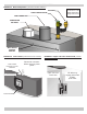
6 - COMBUSTION AIR AND VENT PIPING FIGURE 6-1 Two Pipe Roof Vent 3" (80mm) Minimum 8" (203mm) Minimum 15" (381mm) Maximum 12" (305mm) Minimum Vent Roof Terminations 3" (80mm) Minimum horizontal separation between combustion air intake and vent of same appliance. 8" (203mm) Minimum vertical separation between combustion air intake and vent of different appliances. 15" (381mm) Maximum horizontal length of vent. Minimum vent/intake between different appliances 12" (305mm).
6 - COMBUSTION AIR AND VENT PIPING FIGURE 6-4 Side Wall Concentric Terminal FIGURE 6-5 Side Wall Concentric Terminal Multiple Appliances 1"(2.54cm) 1" (25.4mm) Maximum Roof Overhang 1" (25mm) Maximum Maximum 12" (305mm) Minimum * See Note Below Combustion Air 36"(0.
6 - COMBUSTION AIR AND VENT PIPING FIGURE 6-7 Concentric Roof Terminal Vent Combustion Air Maintain 12"(305mm) US (18"(457mm) Canada) clearance above highest anticipated snow level 24" (610mm) above roof Roof boot/flashing (field supplied) Concentric Vent Roof Terminations Support (field supplied) Note: Support must be field installed to secure termination kit to structure Vent Glue inner vent pipe to prevent recirculation.
6 - COMBUSTION AIR AND VENT PIPING FIGURE 6-10 Flue on Sidewall, Combustion Air on Roof Combustion Air Maintain 12"(305mm) US (18"(457mm) Canada) clearance above highest anticipated snow level 24" (610mm) above roof NOTICE Configurations of single pipe vent with flue on the sidewall, requires a tee as the vent terminal. See figures 6-10 and 6-11.
6 - COMBUSTION AIR AND VENT PIPING 6.7 Side Venting Terminal Requirements of : • USA - National Fuel Gas Code, ANSI 223.1/NFPA 54.
6 - COMBUSTION AIR AND VENT PIPING FIGURE 6-15 Vegetation, Plants & Shrubs Keep vent termination 3’ minimum (0.9m) away from vegetation. Position termination where vent vapors will not damage plants/shrubs or air conditioning equipment. Meters, Regulators, deck, porch Vent termination US only - 4’ (1.2m), Canada - 6' (1.9m) horizontally from, no case above or below, electric meters, gas meters, regulators, and relief equipment, or under deck or porch. Termination 3' (0.
6 - COMBUSTION AIR AND VENT PIPING 6.8 Multiple Boiler Venting Installation • Multiple boiler application boiler can vent individually or use common vent pipes. Table 8 - Minimum Diameter for Individual Boiler in Common Venting System • If boilers vent individually follow guidelines as described in figures 6-1 through 6-7.
6 - COMBUSTION AIR AND VENT PIPING FIGURE 6-18 Condensate Drain 6.9 Condensate Piping • Use materials acceptable to authority having jurisdiction. In absence of such authority: • USA - PVC or CPVC per ASTM D1785/D2845 Cement or primer per ASME D2564 or F493. • Canada - CSA or ULC certified PVC/CPVC pipe, fittings and cement. • Attach PVC tee provided with boiler and field sourced piping to condensate drain at bottom of boiler. See figure 6-18.
7 - GAS SUPPLY PIPING ! CAUTION FIGURE 7-1 Gas Connection WHAT TO DO IF YOU SMELL GAS • Do not try to light any appliance. • Do not touch any electrical switch; do not use any phone in your building. • Immediately call your gas supplier from a neighbor’s phone. Follow gas supplier’s instructions. • If you cannot reach your gas supplier, call the fire department. 7.1 General • Use piping materials and joining methods acceptable to authority having jurisdiction.
7 - GAS SUPPLY PIPING ! DANGER Fire Hazard. Do not use matches, candles, open flames, or other methods providing ignition source. Failure to comply will result in death or serious injury. FIGURE 7-2 Manual Main Gas Shutoff Valve Outside Boiler Jacket 7.3 Leak Check Gas Piping Pressure test boiler and gas connection before placing boiler in operation. • Pressure test over 1/2 psig (3.5 kPa). Disconnect boiler and its individual gas shutoff valve from gas supply system. • Pressure test at 1/2 psig (3.
8 - ELECTRICAL CONNECTIONS ! WARNING 8.1 General Electrically bond boiler to ground in accordance with requirements of authority having jurisdiction. Refer to: • USA- National Electrical Code, ANSI/NFPA 70. Electrical shock hazard. Turn OFF electrical power supply at service panel before making electrical connections. Failure to do so could result in death or serious injury. 8.2 Electric Knockouts (figure 8-1) NOTICE • Five knockouts located on bottom of chassis. A.
8 - ELECTRICAL CONNECTIONS • Outdoor Sensor, if used. A. Provided with boiler. B. Locate outdoor sensor to protect against wind and direct sunlight. Mounting instructions provided with sensor. C. Maximum wire length is 100 ft (30m) for 22 ga. wire, or 150 ft (45m) for 18 ga. wire. D. Connect wires to OUTDOOR SENSOR terminals. Wires are interchangeable.
9 - START UP PROCEDURE 9.1 Fill Boiler With Water And Purge Air NOTICE NOTICE IMPORTANT: Condensate trap must be manually filled with water at initial start up. To maintain boiler efficiency and prevent boiling inside the heat exchanger, flush entire heating system until clean. FIGURE 9-1 Condensate Drain Assembly • Flush heating system, including all heating zones. • Fill boiler with potable water. • Fill boiler and system piping with water (or antifreeze-water solution, if used).
9 - START UP PROCEDURE 9 -2 User Interface 9.3 Program Boiler Control Key Description - Manual Lockout Reset - Enter/Exit user menu - Go to previous screen - Select a menu item - Confirm new parameter value - Scroll up to next menu item - Increase value - Scroll down to next menu item - Decrease value Boiler is factory programmed with following factory default settings, Table 11. Parameters can be adjusted to suit particular application using the user interface. See figure 9-2.
9 - START UP PROCEDURE 9.4 Boiler Start-up and Operational Test 1. Verify air is purged from hydronic piping 2. System test pumps - verify each pump is 9.5 Check Combustion Natural Gas 1. Measure input. English units* operational 3. Verify gas piping • Confirm pressure test. See section 7.3. • Turn off gas to all other appliances. • Activate some heating zones to dissipate heat. • Set boiler on high fire.
9 - START UP PROCEDURE Gas CO2 Min. CO Max. Natural Gas 9.0 9.5 <200ppm Propane 10.0 11.0 <200ppm FIGURE 9-4 Gas Valve - Model 299 MBH NOTICE Contact Technical Support for additional information or assistance. Natural Gas only** 1. Measure input. Compare to table above. Continue to measure input and CO2 until both measured values are within range specified in tables. Propane Gas Most propane systems do not have flow meters. 1. Check CO2. Propane should be between 10% and 11.0%.
9 - START UP PROCEDURE ! WARNING Asphyxiation hazard. Carbon monoxide is odorless, tasteless, clear colorless gas, which is highly toxic. Verify cap is firmly placed on combustion analyzer port to prevent CO emission. Failure to do so could result in death or serious injury. FIGURE 9-5 Combustion Analyzer Port 050/075/100/150/200 Combustion Analyzer Port 9.6 Perform CSD-1 Compliance Test (see paragraph 2.
9 - START UP PROCEDURE 9-8 Control Module J7 Connector 9.7 Complete Start Up Procedure 1. Reset control parameters to operating settings if adjusted to allow startup and operation test. 2. Follow instructions TO TURN OFF GAS TO APPLIANCE J7 Connector (page 42) if boiler is not being placed into immediate operation. 3. Enter installer information on Warranty Registration Card. 4. Gather all instructions, manuals, wiring diagrams, warranty registration card and other supporting information.
10 - OPERATING INSTRUCTIONS FOR YOUR SAFETY READ BEFORE OPERATING ! CAUTION ! WARNING WHAT TO DO IF YOU SMELL GAS If you do not follow these instructions exactly, a fire or explosion may result causing property damage, personal injury or loss of life. • This appliance is equipped with an ignition device which automatically lights burner. Do NOT try to light this burner by hand. • Before operating smell all around appliance area for gas.
11 - GENERAL MAINTENANCE AND CLEANING ! DANGER Before servicing, turn off electrical power to boiler at service switch. Close manual gas valve to turn gas supply OFF to boiler. Failure to comply will result in death or serious injury. ! CAUTION Label all wires prior to disconnection when servicing controls. Wiring errors can cause improper and dangerous operation. NOTICE Verify proper operation after servicing.
11 - GENERAL MAINTENANCE AND CLEANING Figure 11-3 Condensate Trap - 050,075,100,150,200 11.2 Annual Shut Down Procedure • Follow instructions “To Turn Off Gas To Appliance” unless boiler is also used to supply domestic hot water. See section 10. • Drain system completely if system does not have antifreeze when heating system is to remain out of service during freezing weather. Coupling • Drain condensate lines when boiler is to be exposed to freezing temperatures.
11 - GENERAL MAINTENANCE AND CLEANING • Remove ¼-20 hex flange nuts securing condensate collector to heat exchanger using 7/16" deep well socket. See figures 11-3 & 11-4. • Remove condensate collector assembly from heat exchanger and flue pipe. • Flush collector and condensate trap with water. • Follow Burner Inspection Kit instructions to reassemble boiler and resume operation.
12 - RATINGS AND CAPACITIES TABLE 12-1: SEA LEVEL RATINGS NATURAL AND PROPANE GASES Boiler Input Rate (MBH)(1) Size Maximum Minimum 50 75 100 150 200 299 10 15 20 30 40 60 050 075 100 150 200 299 (1) (2) Heating Capacity (MBH)(1)(2) Net AHRI Rating, Water (MBH)(1)(3) AFUE(2) 46 69 91 139 185 273 40 60 79 121 161 239 95.0 95.0 95.0 95.0 95.0 95.0 1000 Btu/hr (British Thermal Units Per Hour) procedures. (3) Net AHRI Ratings based on piping and pickup allowance of 1.15.
13 - TROUBLE SHOOTING 47
13 - TROUBLE SHOOTING Screen Display Explanation Control has blocking error for more than 20 hours in a row. Go to Page 50 Three unsuccessful ignition attempts in a row Go to Page 51 Open gas valve power circuit. May involve high temperature switch, gas valve, or gas valve relay in control module. Go to Page 50 Safety Circuit is open. Go to Page 52 Blower speed does not reach speed calculated by Control Module. Go to Page 53 Control Module internal error.
13 - TROUBLE SHOOTING Screen Display Blocking Error Flue Gas Error E 39 Explanation 3 Go to Page For Troubleshooting Low water cutoff sees no water. Go to Page 56 Flue temperature sensor sees temperature higher than 200°F. Go to Page 57 Return water temperature sensor sees temperature higher than 200°F. Go to Page 58 Control board internal error. Power down then power up boiler. If error repeatedly occurs replace control module.
YES YES Replace Harness NO Disconnect harness from Gas Valve. Does each wire have continuity between Gas Valve and Control Module NO Replace Gas Valve Replace Control Module YES Connect harness NO YES Replace Supply Sensor Is supply pipe (copper pipe at top of boiler) hot? NO YES Boiler has been dry fired. System has too much air. Close manual gas valve (shut off gas). Purge air from system, wait for system to cool. NO Unplug connector on supply sensor.
13 - TROUBLE SHOOTING 51
Fix Loose Connections YES NO • Flush system if water is dirty. • Verify water flow in system piping YES Replace Broken Switch Check high limit and surface temperature switches NO Is Heat Exchanger surface hot? NO Wait for boiler to cool down. Let all zones run until water temperature drops. YES Is boiler supply pipe (above heat exchanger) hot? Boiler fired without enough water flow through heat exchanger. Heat exchanger is over heated.
13 - TROUBLE SHOOTING 53
Disconnectharness harness from from High High Disconnect TemperatureSupply SupplySwitch Switch and and Temperature ControlModule ModuleJ13. J13. Control Continuity from J13-5 to Switch Check continuity of both purple 1? Continuity J13-6for toboth wires.
Turn Shutoff Turn offGas manual gas Valve clockwise shutoff valve. to closed position. Follow Follow instructions instructions TOTO TURN OFF GAS TURN OFF GASTO APPLIANCE. Replace TO APPLIANCE. Replace Valve. Gas Gas Valve. Replace Control Module Inspect burner through sight glass. Is flame present? YES NO _P___ Blocking Error E35 False flame detect Replace Control Module YES Replace Flame Sensor and Burner NO Follow Operating Instructions to initiate boiler operation.
Repair System Piping, remove any remaining air in system. 56 YES NO Connect harness to Transformer. Disconnect harness from Low Water Cutoff.
E 393 57 YES Replace Control Module NO Use thermal couple to measure flue gas temperature through sampling port. Is the measured temperature and flue temperature reading on User Interface significantly different? NO Replace Flue Gas Sensor Boiler is over fired. Wait for boiler to cool. Fix flow rate problem if any, purging all air out of the system. YES Read flue gas temperature on User Interface.
Replace Control Module Correct wiring NO YES Replace Return Water Sensor Install Heat Exchanger Pump in proper orientation NO Is Heat Exchanger Pump properly oriented? (Pump arrow pointing down?) NO Disconnect harness from Return Water Sensor. Measure resistance using digital ohm meter. Is resistance between 950 to 33,000 ohms? NO YES Remove all liquid from connector. Check for leaks. Repair all leaks. YES Unplug molex connector on return sensor.
Fix the connection. YES 59 Boiler is operating properly Replace Control Module Replace blower motor. Does this correct the problem? NO YES NO These error messages are displayed when the control board detects fault in blower motor system. Check wire connector to blower. Check connector J9 on control board.
YES 60 °F 50 to 90 90 to 130 130 to 150 150 to 200 °C 10 to 32 32 to 54 54 to 66 66 to 94 2K to 1K ohms 2K to 3K ohms 3K to 9K ohms 9K to 24K ohms Resistance Supply Water Sensor Resistance Chart Replace Control Module YES YES YES Replace Supply Water Sensor NO Replace Wires NO Insert Harness NO Is harness plugged into Supply Water Sensor? Is harness plugged into Control Module J5? _P___ Blocking Error E51 Supply Sens Open Disconnect J5 from Control Control Module.
YES Replace Control Module Replace Wires NO Replace Return Temperature Sensor NO MeasureReturn Return Temperature Temperature Measure Sensor resistance withwith digital Sensor resistance meter. Estimate Sensor digital meter. Estimate temperature. Do temperature Sensor temperature.
Supply Water Temperature Sensor Resistance Chart Disconnect wire harness from High Temperature Supply Switch. Measure resistance across terminals 2 and 4.
YES Replace Control Module NO Disconnect harness from Control Module J5. Measure resistance between brown wires at terminals J5-4 and J512. Is resistance less than 50 ohms? NO Replace wires Replace Return Water Sensor YES Disconnect harness from Return Temperature Sensor. Measure resistance across sensor terminals.
14 - WIRING DIAGRAM 14.
14 - WIRING DIAGRAM 14.
14 - WIRING DIAGRAM 14.
14 - WIRING DIAGRAM 14.
15 - GLOSSARY • ANSI - American National Standards Institute, Inc. oversees creation and maintenance of voluntary consensus standards, including ANSI Z21.13/CSA 4.9: Gas-Fired Low Pressure Steam and Hot Water Boilers. • GAS PIPE SIZES - Table 14 NATURAL GAS • ASTM - American Society for Testing and Materials. ASTM International is one of largest voluntary standards development organizations in world trusted source for technical standards for materials, products, systems, and services.
15 - GLOSSARY • QUALIFIED AGENCY - Any individual, firm, corporation, or company engaged in and responsible for: • Installation, testing, or replacement of gas piping, or connection, installation, testing, repair or servicing of appliances and equipment. • Experienced in such work. • Familiar with all precautions required. • Complies with all requirements of authority having jurisdiction.
APPENDIX A - CONTROL MODULE 1.1 Introduction Operation with LCD character display module Boiler is equipped with programmable electronic control and user interface module. 1.2 Operation • Display: 4 x 20 character LCD screen to show boiler status. • Function Keys Key Description - Manual Lockout Reset - Enter/Exit user menu - Go to previous screen - Select a menu item - Confirm new parameter value - Scroll up to next menu item - Increase value - Scroll down to next menu item - Decrease value 1.
APPENDIX A - CONTROL MODULE 1.4 Sequence of Operation Operational State No User Interface Display Standby: No Demand Heat Demand? Explanation Boiler operates in standby mode until demand for Central Heat (CH) or Domestic Hot Water (DHW) is detected. Yes CH or DHW pump is turned on based on type of heating demand. DHW CH Pump on Supply Temperature
APPENDIX A - CONTROL MODULE 1.4 Sequence of Operation Operational State User Interface Display After 2 seconds Flame Detected? Yes If flame detected before Gas Valve opens during ignition boiler will lockout. Lockout Error A21 Please refer to troubleshooting guide. Note: 5 Ignition trials, then Lockout A01 No Gas Valve Energized Gas Valve energized to deliver air/fuel to burner.
APPENDIX A - CONTROL MODULE 1.5 User Menu Explanation STANDBY User Interface Display Boiler operates in standby mode until demand for Central Heat (CH) or Domestic Hot Water (DHW) is detected. User Menu (Press Menu botton on user interface to access User Menu) User Menu User Menu structure includes: • ‘Boiler Status’ submenu– User can monitor general boiler status parameters such as sensor temperatures and pump operation.
APPENDIX A - CONTROL MODULE Explanation User Interface Display Adjust CH set point to hydronic system design while in Operating in CH Mode = 0 (CH with Thermostat) or 3 (Permanent Demand). In CH Mode = 1 (CH with Thermostat and Outdoor Reset) or 2 (CH with Full Outdoor Reset). Display will change to ‘OD Reset Setpoint’ and cannot be changed. Controller calculates set point based on outdoor temperature.
APPENDIX A - CONTROL MODULE Explanation User Interface Display Installer Menu Installer Menu structure includes: • User 'Menu' can be accessed by pressing 'Menu' key on user interface. Installer Menu • Installer 'Menu' can be accessed by first pressing and holding the 'Enter' key continue to hold and at the same time press and hold the 'Menu’ key for 5 seconds. (You must press and hold the 'Enter' key first then press and hold the 'Menu' key).
APPENDIX A - CONTROL MODULE Explanation User Interface Display Installer Menu Control module logs successful and failed ignition attempts. Information accessed in ‘Ignition Attempts’ Screen as shown. Ignition attempts are stored in non-volatile memory and are retained in event of power failure.
APPENDIX A - CONTROL MODULE Explanation User Interface Display Boiler Status Boiler stores information regarding total CH and DHW run time in hours. Data stored in non-volatile memory and retained in event of power failure. Boiler logs last 16 blocking errors and 16 lockout errors in non-volatile memory. Information retained in event of power failure. Most recent blocking error code and its text description displayed with elapsed time in hours since logged.
APPENDIX A - CONTROL MODULE Explanation User Interface Display Two pump modes are available: 1. Pump Mode = 0 ‘CH or CH&DHW’ • In this mode either the CH or DHW pump terminal is energized depending on the type of demand (CH or DHW). • CH and DHW pumps are never energized at the same time. • In the case of a simultaneous call for both CH and DHW, the energized pump depends on whether the boiler is currently supplying the CH or DHW demand. Refer to DHW Priority settings below.
APPENDIX A - CONTROL MODULE Explanation User Interface Display 4. Central Heating (CH) modes available: • CH Mode = 0 ‘CH with Thermostat’ • Boiler will attempt to satisfy CH demand while CH thermostat input is closed. • Boiler will modulate its firing rate to maintain CH set point and match system heat load.
APPENDIX A - CONTROL MODULE Explanation User Interface Display If outdoor temperature is greater than Warm Weather Shutdown Temperature, demand for CH blocked and pumps stopped. Allowed Range: 35°F to 100°F (2°C to 38°C) Default Setting: 70°F (21°C) Boiler capable of operating in Outdoor Reset Mode when included Outdoor Sensor is connected and proper CH Mode selected.
APPENDIX A - CONTROL MODULE Explanation User Interface Display Outdoor reset boost function increases CH set point by increment (‘Temp’) if CH demand continues beyond pre-set time limit (‘Time’). CH Settings CH set point will continue to increase until set point reaches 195°F / 91°C Allowable Temperature Increment: 0..36 °F (0..20 °C) Default Temperature increment: 0 °F (10 °C) Allowable Time Delay: 1..
APPENDIX A - CONTROL MODULE Explanation DHW Settings User Interface Display Maximum time boiler operates in DHW mode limited by DHW Maximum Priority Time Setting. Priority timer starts when both CH and DHW demand is present. Boiler will switch from DHW back to CH operation after Maximum Priority Time has elapsed. CH demand then has priority until Maximum Priority Time has elapsed. Allowed Range: 1 to 60 Minutes Default Setting: 30 Minutes Process repeats until either CH or DHW demand satisfied.
NOTES 15 83
IMPORTANT In accordance with Section 325 (f) (3) of the Energy Policy and Conservation Act, this boiler is equipped with a feature that saves energy by reducing the boiler water temperature as the heating load decreases. This feature is equipped with an override which is provided primarily to permit the use of an external energy management system that serves the same function.