
User Manual


20
CHECKING AND ADJUSTING
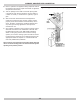
Adjust Steam Pressure Control
• Steam pressure limit control (pressuretrol) shuts
off gas to main burners when steam pressure in
boiler reaches cut-off setpoint (i.e. sum of cut-in and
differential setpoints).
• Burners rere when steam pressure drops to cut-in
setpoint.
• System pressure requirements are based on size and
condition of pipes, and load.
• Cut-in setting of pressuretrol should never be less than
twice system pressure drop for good system operation.
A. In typical single family residence with clean one-
pipe heating system and cast iron radiation, cut-in
is usually set at minimum setting, i.e. 1/2 psi.
• Steam radiation is sized based on square feet of
equivalent direct radiation (EDR). This is based on
steam pressure in the radiator of just less than 2 psi.
• Set differential adjustment at 1 psi, i.e. steam pressure
required in radiators. Results in cut-off setpoint of 1½
psi.
• Larger systems or other types of systems such as two
pipe systems, or systems with convectors or fan coil
units, pressuretrol settings need to be determined on
system-by-system basis.
• Cut-in setpoint is determined by system pressure drop
to furthest radiator or terminal unit. Double system
pressure drop as safety factor, resulting in the rule
cut-in setting should never be less than twice system
pressure drop.
• Differential setpoint is steam pressure required at
terminal heating units.
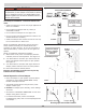
Boiler will now operate in correct pressure range. It
maintains enough steam pressure to send steam out to
furthest radiator, and not go over optimum steam pressure
required at the radiators.
Checking Controls
Low Water Cut-Off
A. Turn off power to boiler or turn thermostat down to
lowest setting.
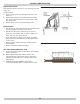
B. Drain water to below visible bottom of water gauge
glass. Turn power on and turn thermostat to call for
heat.
C. Gas valve opens for approximately 10 seconds
(time delay on probe type LWCO), gas valve will
close and red indicator illuminates on LWCO.
D. When water is restored, it waits 30 seconds before
reactivating burner circuit.
Boiler Equipped With Optional WF-2U-24 Water
Feeder
E. Continue thermostat call for heat after low water
cut off recognizes low water condition.
F. One minute time delay, water feeder starts feeding
water to boiler.
G. Feeder feeds for one minute, and then goes into
another one minute waiting period.
H. Cycle of alternately waiting and feeding will repeat
until :
• For Model 67D-1 oat type low water cutoffs - as
the water level raises the oat above the burner
cut off switch level, the burners should ignite. The
water feeder remains powered until the water
level raises the oat to the water feeder switch
level, satisfying the water feeder.
• For probe type low water cutoffs - the water level
will rise until water in the boiler makes contact
with the probe, satisfying the water feeder, and
igniting the burners.
I. In either case, one and two inches of water should
be visible in glass gauge when both water feeder is
satised, and burners are allowed to ignite.
• Time delays in feed cycles are designed to prevent
boiler from ooding due to slow return lines.
• To check pressure limit, run boiler until pressure
reaches system demand. Turn pressure screw and drop
pressure setting until boiler shuts down. This shows the
pressure limit is operating properly.
• Refer to control manufacturer’s instructions for more
information.
Check Thermostat Operation
Thermostat set above temperature indicated on
thermometer, boiler should ignite.
Verify thermostat turns boiler off when room temperature
reaches selected setting and starts boiler operating when
room temperature falls few degrees.
Set thermostat for desired temperature. Conditions in your
home and location of thermostat will govern this setting.