Instruction Manual PERFECT BINDER MODEL: DB-280, DB-200, DB-660, DB-700 Duplo Taiwan Corporation TEL:886-2-27212117 FAX:886-2-27211669 8F., NO.2, SEC.4, CHUNG HSIAO E.RD.
Table of Contents Page 0. Cover/Table Of Contents 2 1. SAFETY INSTRUCTION 8 1.1 SAFETY REGULATION 9 1.2 WARNING PLATE 11 1.3 LOCATION OF SAFETY SIGNS ON THE PRESS BRAKE IS SHOWN IN THE FIGURE BELOW 12 1.4 NAME PLATE 13 2. SPECIFICATION 14 2.1 14 2.2 SPECIFICATION MACHINE NOISE 2.3 FUNCTION OF THE MACHINE 17 2.4 LEGEND OF THE MACHINE 18 2.5 MACHINE DIMENSION 19 3. INSTALLATION 23 3.1 SAFETY RULES FOR MACHINE MOVEMENT 23 3.2 LIFTING THE MACHINE/DRAWING 24 3.
~3~
~4~
~5~
~6~
~7~
1 Safety Instruction General Safety Regulation Warning Be careful of the following items that may cause injury or damage. •Do not place tiny items on top of the machine to avoid dropping them into the machine. •Pay close attention to the warning signs on the machine that indicates a dangerous or “no-touch” area of the machine. •Keep hands and fingers away from glue tank and notching station. •Use only the suggested hot melt glues with the following characteristics: Application temperature: 260 F (126.
1.1 Safety Regulation •KNOW YOUR MACHINE. For your own safety, read the owner's manual carefully. Learn its application and limitations as well as specific potential hazards pertinent to this machine. •KEEP GUARDS IN PLACE AND IN WORKING ORDER. •REMOVE ADJUSTING KEYS AND WRENCHES. For habit of checking to see that keys and adjusting wrenches are remove from the machine before turning it on. •KEEP WORK AREA CLEAN. Cluttered areas and benches invite accidents. •DO NOT USE IN DANGEROUS ENVIRONMENTS.
•Protective guards and shields must be in place at all times unless that specific part requires servicing. •Never clean or remove chips while the machine is running. •Do not remove or alter warning labels and replace any that become obscured. Warranty If any part is proved to be defective within ONE YEAR from the date of purchase then the manufacturer or distributor shall repair or replace the part provided the defective part is returned immediately to the manufacturer or distributor.
1.2 Warning Plate This machine has warning symbols attached on it as shown below to ensure proper and safe operation. These symbols are used on the machine to indicate points or instances of specific danger to operating personnel. Make sure to memorize these symbols and bring them to the attention of others as and when necessary. Do not remove safety symbols from the machine.
1.
1.
2 Specification 2.1 Specification Model DB-280 12.6” x 15.75” ( 320mm x 400mm ) Maximum Book Size Minimum Book Size 3.15” x 1.97” ( 80mm x 50mm ) Maximum Binding Thickness 1.6” ( 40mm ) Glue Warm Up 40 minutes ( varies depending upon glue type ) Glue Warm Up in Stand-by Mode 5 minutes Cycle Speed 360 cycles per hour Production Speed Up to 200 books per hour Power Source 110V, 60 Hz ( Option: 220V, 50 Hz ) Power Consumption 10 Amps. Machine Weight 262 Machine Dimension 49.
Model DB-660 11.7” x 15.53” ( 297mm x 420mm ) Maximum Book Size Minimum Book Size 5.7” x 5.51” ( 145mm x 140mm ) Maximum Binding Thickness 2.3” ( 60mm ) Glue Warm Up 40~50 minutes ( varies depending upon glue type ) Glue Warm Up in Stand-by Mode 5 minutes Cycle Speed 570 cycles per hour Production Speed Up to 200 books per hour Power Source 110V, 60 Hz ( Option: 220V, 50 Hz ) Power Consumption 10 Amps. Machine Weight 210~230 Kg ±3 Kg Machine Dimension 54.3”(L) x 25.6”(W) x 40.
2.2 Machine Noise DECLARED NOISE EMISSION VALUES in accordance with ISO 7960. Operating Declared A-weighted Sound Power Level, Lward, in dB re 1 pW 81.8 Declared A-Weighted Emission Sound Pressure Level , lpAd , in dB re 20 μPa , at the operator’s position. 68.8 The values are determined according to specific test code ISO 3746. The figures quoted are emission levels and are not necessarily safe work levels, whilst there is a correlation between emission and the exposure level.
2.3 Function of the Machine 1. Provided a flat surface for the book block, when there are being placed into the clamp station. It also provides the nipping force to form the cover around the spine of the book. 2. Holding the book block for the notching, gluing, and nipping processes of bookbinding. 3. Provides driving power to move and locate the clamp station over the glue drum and notching station, then return it back to the nipping station for covering and binding.
2.
2.
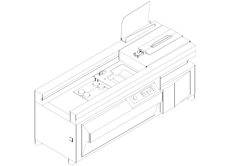
DB-200 ~ 20 ~
DB-660 ~ 21 ~
DB-700 ~ 22 ~
3 Installation 3.1 Safety Rules for Machine Movement SETTING THE MACHINE IN PLACE •The haulage of the machine to the installation place is done with the crane or forklift. •Before unloading the machine, conduct a complete inspection of any damage which might have been caused during transportation. •Before placing the machine on the production floor, make sure that the floor base is thick and strong enough to endure mechanical vibration and to support the weight of the machine for a long time.
3.
3.3 Selection of Installation Location 1. Install the machine on a level safe, firm and solid table which will hold the weight of the machine. 2. Keep the machine away from the direct sunlight and heat sources such as stoves, heaters and radiators. 3.4 Installation/Drawing Note: You must remove the three red shipping brackets before installing your DB-280 The procedures for installation: Remove the red shipping bracket located on the left side of the clamp station as shown.
3.5 Installation and Leveling 3.5.1 Tools: adjust screw by screwdrivers , Allen wrench 3.5.2 The main machine is calibrated by level gauge to hundredth precision 3.6 Power Supply Requirement Insufficient voltage from factory power source may affect the power output of the motor and the function of the controller. It is important to connect this machine to the correct voltage in the factory power source. Use only an independent power source. Table for power supplies requirement: 3.
3.8 Check Connection of Power Wires After the power wires have been connected it is necessary to check if the power wires are connected to the correct connection points.
4 4.
4.
No. Name Description LED Display / Example 1 EMERGENCY Stop all the actions of the machine. Except when “HOT” shows on the LED DISPLAY. “STOP” (flashing) 2 STAND BY / LED Temporarily lowers the temperature of glue tank so it won’t burn the glue when the machine is not operated. STBY00 3 CLOSE Close clamp. 4 LED DISPLAY The amount of books bound. ____100 1)The amount of books bound. 2) Operating status. BIND 3) Perform self-test and stir glue. the hot melt S-TEST 4) Error messages.
4.4 Operation Procedure (Using the DB-280) START UP: Turn ON the power switch of DB-280 as shown. ( where “I” for ON; “O” for OFF ) The heater of DB‐280 will automatically heat the glue to the preset working temperature and display the status of the heating processes.The 4 leftmost spaces of LED: the status of heating process ( COLD, WARM, or HOT ).The 2 rightmost spaces of LED: The elapsed time of heating. Start melting the glue.
4.4.1 Glue Adjustment The glue level may require adjustment when the thickness of the book or pad varies. Use the following book spine illustrations for guidelines. • Increasing the holt-melt glue when Hollow middle OR Round • Decreasing hot-melt glue when Too much glue on both sides OR Nail head Adjusting the glue level : 1. Turn the glue adjustment lock knob counter clockwise to loosen. 2. Increase the amount of glue by sliding the knob to the right at the appropriate position. MIN MAX 3.
4. Turn the knob clockwise to lock the setting Note that the thickness of the cover sheet is an important factor for you to make a good spine. Use only the suitable thickness of the cover sheet associated with the appropriate glue-meter position to make a good book.
4.4.2 Replenishing Glue Tank CAUTION: Great care must be taken when handling hot molten glue. Be sure not to place an excessive amount of glue in the tank at one time. Keep it at such a level that the glue will not go over the redline in the tank while the application drum is rotating. This will prevent glue from spilling out of the tank Glue Replacement 1. Warm up the DB-280 as described in the STARTUP section on page 5. 2.
4.4.3 Manual Mode After the “STARTUP” procedures, the DB-280 will automatically set itself MANUAL operation and flashing "LOAD BOOK" display. Note that the “NOTCH” LED is ON. 1 (1) Press the “OPEN” button and place the book block inside the clamps. Be sure to follow the label instructions on the clamp to load the book block to the RIGHT of the red line, then slide the book block to the far LEFT of the clamps and you will see the flashing "PUSH CLOSE" display.
After the first notching process, the clamp station will remain to the left side of DB-280 and the LED display of the control panel will display and flash "LOAD COVER". 2 3 4 Center the cover sheet and adjust the side guide: Measure the width of the book plus half the thickness of the spine. Then set side guide accordingly. Place the cover on the nipping station, the “START” LED will be lit and flashing "PUSH START".
4.4.4 Auto Mode Note: All books done in this mode must be same thickness. 1 In the MANUAL mode, make one book. Centering the cover to the centered point and adjust the side guide. 2 Press “FUNCTION” button to switch to “AUTO” operation. The “AUTO” LED will be lit and display flashing "LOAD BOOK" as shown. Note: 3 The “NOTCH” LED is ON. Step 1: Load book to the RIGHT of the red line. Step 2: Slide the book to The far LEFT. (1) Press the “OPEN” button.
4 Place the cover sheet onto the nipping station when the display flashing "LOAD COVER". The clamp station will automatically move back to the position above the nipping station and start the binding process for the book block and cover sheet. Note: If you accidentally remove or drop the cover sheet during the clamping station return to the nipping station, the control panel will show “COVER?”.
4.4.5 PADDING MODE: “PAD” is one of the DB-280 operations that apply to special binding applications such as binding without cover sheet. 1 Press “FUNCTION” button to switch to “PAD” operation. The “PAD” LED will be lit and display flashing "LOAD PAD" as shown. Note: The “NOTCH” LED is normally OFF. But you can press “NOTCH” button to actuate it, if desired. 2 (1) Press the “OPEN” button.
(2) Having moved to the left position of DB-280, the clamp station will automatically move back to the right position and display "WAIT..". (4) Wait for a few seconds until the LED display of control panel displays “PUSH OPEN” as shown. 4 Then press the “OPEN” button to open the clamp so that you can withdraw the bound pad block. Meanwhile, the LED display of control panel will count once for the total binding amount. Then the control panel will display and flash "LOAD PAD" for padding next pad.
4.4.6 STANDBY MODE Press “STANDBY” button, the DB-280 will temporarily lower the temperature of glue tank so it won’t burn the glue when the machine is not operated. The LED displays "STBY00" as shown below. Where "00" is the timer display for the duration of the standby period. Press “STANDBY” button again when the “STANDBY” LED is on, the DB-280 will reheat the glue tank to the working temperature, then the “READY” LED will be lit and waiting for your desired operation.
4.4.7 TAPE MODE 1 BEFORE USING TAPE MODE INSTALL FOUR OPTIONAL BLOCK PARTS. Press “TAPE” button,LED Display 2 “TAPE” “MODE"instead of ”LOAD”“BOOK” After clamp station goes to left,LED display shows ”LOAD” “TAPE” Press “START” after putting tape, book go back right side then finish the tape mode ATTENTION: It’s same operation in manual or auto mode,please put tape in right postion then press “START” 3 TR1 SETTING Press “START” and “TAPE” together,set TR1 only.
4.4.8 CASING UNIT CONTROL The casing unit is used for adjusting the distance between book sheets and hard cover, adjusting range 0~10mm Tuning angle 0~180degrees Release the M4 screw first, after 4.4.9 adjusting tight the M4 screw. VACUUM DUST REMOVAL SYSTEM When blade cutting,it brings paper dust, so use vacuum dust removal system to clean. The vacuum pipe size :4” 4.4.
4.5 Adjustment of the Machine/Components 4.5.1 Notching Station Function The purpose of notching is to enhance the solidification of the bookbinding. The notching blade makes numerous cuts on the spine of the book so that the melted glue can penetrate the binding area. Inner Pages Cuts Hot‐Melt Glue Adjustment In order to get appropriate depth of the cuts and the precision of the center path for clamp station, the notching station can be adjusted to the up, down, right, and left positions as shown.
Changing the blade 1. Open one side of the notching station 2. Loosen the blade screw and remove the old blade 3. Install the new blade as shown, then set the height of the blade about 3mm above the surface of notching wheel 4.
4.5.2 Glue Tank Function Providing a layer of melted glue on the spine of the book so that cover and pages can be bound together . The glue scraper of glue tank controls the quantity of the melted glue on the glue drum while the glue meter controls the thickness of melted glue that is applied to the spine Adjustment • Adjusting the gap for the glue meter: 1.) Set the glue-adjusting knob to the left ( MIN ) position 2.
• Setting the glue -adjusting knob to the appropriate positions: Normally, the indicator is set at 1/3 to 1/2 of the arrow mark. • Controlling the quality of a book by means of the glue meter: Note that the thickness of the cover sheet is an important factor for you to make a good spine. Use only the appropriate thic kness of cover sheet to make a good book. 1.) Decrease the melted glue when: 2.
4.5.3 Nipping Station Function Provided a flat surface for the book block, when there are being placed into the clamp station. It also provides the nipping force to form the cover around the spine of the book Adjustment 1.) During the nipping process, the nipping plates must exert an even pressure on the cover in order to form a spine 2.) The nipping swing arms provide this pressure Open the nipping station, then turn the swing arms counter-clockwise to the position shown.
• Position change on the position disc of nipping station There are three positions of the nipping station for executing the clamping, the cover, and the nipping processes. The LED of the sensor (LS3 or LS4) goes on when the notch of position disc travels through the trench of the sensor as shown below: 1.) Clamping: when the bearing is at the highest point 2.
3.) Nipping: when the bearing is at the sub-high point If the spine is not being nipped evenly, adjust the nipping plates as follows: • Adjusting on the Nipping Plates 1.) Push each side of nipping plates to find out which side is too tight. 2.) Then use the nipping plate screws to do the fine adjustment until both sides have the same tension. Note that you can use the“MOTOR2” of “TEST2” to verify the nipping plate position before tightening them.
• Position Adjustments on Nipping Station (A) The level of nipping station should be adjusted evenly on the corresponding ends to prevent tilting the nipping station surface, by level adjusting screws. (B) The centerline of the nipping station must match the projected centerline of the clamp station by the front/rear adjusting screws. (C) The position of cover can be adjusted by the cover position adjusting screws, along with the position of LS1.
4.5.4 Clamp Station Function Holding the book block for the notching, gluing, and nipping processes of bookbinding. Adjustment The acceptable spine of a book and the shape of book block after being clamped are shown below. If you find different shapes such as “round”, “hollow” and “nail head” for one end or both ends, remove the clamp covers, then adjust the screws on both clamps. How to adjust 1.
LL and LR corners are nail head: it means that the left spine of the book should be lift up to make the left side of the spine rounder. So you can increase adjustment on both NON-OP Plate1 and OP Plate 1,and making book to see LL and LR corners are ok or not. LL corner is nail head: it means that the LL corner should be lift up to make the LL corner rounder, So you can increase adjustment on NON-OP Plate 1,, and then making book to see LL corner is ok or not.
LL and LR corners are round: it means that the left spine of the book should be push down to make the left side of the spine to be more right angle. So you can increase adjustment on both NON-OP Plate 2 and OP Plate 2, and then making book to see LL and LR corners are ok or not. LL corner is round: it means that the LL corner should be push down to make the LL corner to be more right angle, So you can increase adjustment on NON-OP Plate 2,and then making book to see LL corner is ok or not.
4.5.5 Driving Section Function Provides driving power to move and locate the clamp station over the glue drum and notching station, then return it back to the nipping station for covering and binding. Adjustment Adjust tensioner to eliminate any slack in chain 5 Maintenance 5.1 Day/Month/Year Maintenance Daily Cleaning Procedures After you have finished using the binder for the day, follow the following steps: 1.Close the clamps while the LED display flashing "LOAD BOOK" or "LOAD PAD". 2.
1. Open the clamps to the maximum position then turn off the power of the machine. 2. Take apart the clamps from the clamp station. 3. Clean the residual glue that might be on the clamps. 4. Install the clamps to the clamp station. 5. Turn on the power of the machine. 6. Clamp some inner pages to see if the clamps have been installed properly. If clamp adjustment need, please refer to A1 section of Appendix for details. (2) Notching Station This is a monthly maintenance.
~ 57 ~
~ 58 ~
~ 59 ~
5.4 Test Of Safety Devices • TEST1 – Operation Test: Press and hold down the “FUNCTION” and “START” buttons, then turn the power on. You should see the “TEST1” in the LED display.
6 Electric 6.1 Safety Rules For Electrical Control System 1.) Only personnel who are properly trained and have adequate knowledge and skill should undertake all electrical/electronic troubleshooting and repair. 2.) Do not alter or bypass protective interlocks. 3.) Before starting, read and observe all warning labels. 4.) When trouble shooting make sure the power source has been disconnected and main switch has been locked. 5.) Take extra precautions in damp areas to protect you from accidental grounding.
6.
~ 63 ~
~ 64 ~
~ 65 ~
~ 66 ~
~ 67 ~
~ 68 ~
6.3 Electrical Component List Function Symbol Specification 1 Motor M1 4RK25GN 2 Motor M2 5TK50GN 3 Motor M3 5IK40A 4 Motor M4 2GN30K 5 Power supply GS1 6 EMG STOP SB1 1A1B QF1 4P 7 Circuit breaker 8 heater U1 9 Temp switch SQ1 E.G..