Venting System For Direct Vent Gas Stoves and Fireplaces DirectVent Pro Installation Instructions
A MAJOR CAUSE OF VENT RELATED FIRES IS FAILURE TO MAINTAIN REQUIRED CLEARANCES (AIR SPACES) TO COMBUSTIBLE MATERIALS. IT IS OF THE UTMOST IMPORTANCE THAT DOUBLE WALL DIRECTVENT PRO BE INSTALLED ONLY IN ACCORDANCE WITH THESE INSTRUCTIONS. IMPORTANT: Read through all of these instructions before beginning your installation.
For the most up-to-date installation instructions, see www.duravent.com CONTENTS DirectVent Pro Venting System for Direct Vent Gas Stoves and Fireplaces Application | Warning | Safety & Installation Precautions . . . . . . . . . . . . . . 4 Options | Planning Your Installation . . . . . . . . . . . . . . . . . . . . . . . . . . . . . . . . 5 Horizontal Installation . . . . . . . . . . . . . . . . . . . . . . . . . . . . . . . . . . . . . . . . . . . 6 Snorkels . . . . . . . . . . . . . . . . . . . .
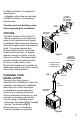
APPLICATION nearby combustible surfaces. Be sure to check the vent termination clearance requirements from decks, windows, soffits, gas regulators, air supply inlets, and public walkways, as specified in these installation instructions and local building codes. • The gas appliance and vent system must be vented directly to the outside of the building, and never be attached to a chimney serving a separate solid fuel or gas-burning appliance.
by M&G DuraVent or the appliance manufacturer. • Installation other than as instructed by M&G DuraVent or the appliance manufacturer. ROUND HORIZONTAL TERMINATION CAP SHOWN PIPE SECTION Consult your local building codes before beginning the installation. OPTIONS The M&G DuraVent DirectVent Pro offers a complete line of component parts for both horizontal and vertical installations. Many items are offered in decorative black as well as galvanized finish.
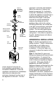
VERTICAL HIGH WIND TERMINATION CAP SHOWN STORM COLLAR ROOF FLASHING CEILING FIRESTOP ROUND CEILING SUPPORT/WALL THIMBLE COVER CATHEDRAL CEILING SUPPORT BOX PIPE SECTION important to note the wall thickness. Select the amount of vertical rise desired or required, for “vertical-tohorizontal” installations (verify that it is within the appliance manufacturer’s minimum and maximum limits).
Notes: (1) Twist-lock procedure: Line up locking lugs on male and female ends of pipe sections. Insert the male end of pipe into the female end until the locking lugs are covered. Twist the female end clockwise an eighth of a turn to lock sections together (Fig. 5). Screws are not required to secure the joint, but are acceptable provided they do not penetrate the inner wall of the vent pipe. (2) Horizontal runs of vent pipe must be supported to prevent any downward sags.
Table 1 DirectVent pro framing or cutout dimensions Stock number 46DVA-WT 46DVA-WTS 46DVA-WTU 46DVA-CS 46DVA-FS 46DVA-WFS 46DVA-VSS 46DVA-CF 46DVA-CFK 46DVA-CFKS 46DVA-VSK 46DVA-VSKS 46DVA-IS 58DVA-WT 58DVA-WTS 58DVA-WTU 58DVA-CS 58DVA-FS 58DVA-WFS 58DVA-VSS 56DVA-VSK 58DVA-CF 58DVA-CFK 58DVA-IS component description Wall Thimble Wall Thimble (Small) Wall Thimble Universal Ceiling Support Fire Stop Wall Fire Stop Vinyl Siding Standoff Counter Flashing (Assembled) Counter Flashing (4pc.
(e) Clearance to an outside corner: as tested by appliance manufacturer. (f) Clearance to an inside corner: as tested by appliance manufacturer. (g) Not to be installed above a meter/ regulator assembly within 3 feet horizontally from the centerline of the regulator. (h) Clearance to a service regulator vent outlet: 6 feet minimum. (i) Clearance to non-mechanical air supply inlet to a building or the combustion air inlet to any other appliance: 12 inches minimum.
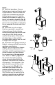
Snorkels SHEET METAL SCREWS WALL THIMBLE COVER Figure 8 WOOD SCREWS Figure 9 inserting the Pipe Section into the cap assembly. It is important that the Pipe Section extends into the back of the Termination Cap with a minimum overlap of 1-1/4 inches. Use the two sheet metal screws provided to secure the Pipe Section to the back of the Termination Cap. The Wall Thimble Cover will cover the screw heads (Fig. 8). Step 7.
SNORKEL OPTIONAL DVA-WTU ADJUST AND SECURE TELESCOPING THIMBLE SLEEVES WITH SCREWS 12" MINIMUM Figure 10 SNORKEL WALL THIMBLE COVER 12" MINIMUM ADEQUATE DRAINAGE Figure 11 11
VINYL SIDING, STUCCO OR OTHER SIDING MATERIAL VINYL SIDING INSTALLATION ASSEMBLE VINYL STANDOFF/COUNTER FLASHING IN SPECIFIC ORDER 1 2 4 3 CUT EXTERIOR OF WALL AS REQUIRED IN TABLE 1 4 PC.
clockwise, place the left side, the bottom side, and then the right side around the opening in the siding. Refer to Figure 12. With the 4 pieces in place secure the pieces together using the pre-drilled holes and the screws provided. Seal around the inside corners of the Vinyl Siding Standoff to help ensure a weather tight installation. Attach the Horizontal Cap to the Vinyl Siding Standoff.
CEILING JOISTS MARK LOCATION CUT AND FRAME MARK AND DRILL FRAMING PLUMB BOB CEILING JOISTS CUT AND FRAME DECORATIVE CEILING SUPPORT COVER 1 1/2" WOOD SCREWS Figure 13 Figure 14 Step 1. Check the appliance manufacturer’s installation instructions for required clearances (air spaces) to combustibles when passing through ceilings, walls, roofs, enclosures, attic rafters, or other nearby combustible surfaces. Do not pack air spaces with insulation.
(Fig. 13). Determine if ceiling joists, roof rafters, framing or other materials will obstruct the venting system. You may wish to relocate the appliance, or to offset, to avoid cutting load-bearing members. Step 3. To install the Round Ceiling Support/Wall Thimble Cover in a flat ceiling, refer to Table 1, page 8 and cut a square hole in the ceiling (unless otherwise specified by the appliance manufacturer) centered on the hole drilled in Step 2. Frame the hole as shown (Fig. 14). Step 4.
Table 2 Roof Pitch Minimum HeightMinim Flat to 7/12 Over 7/12 to 8/12 Over 8/12 to 9/12 Over 9/12 to 10/12 Over 10/12 to 11/12 Over 11/12 to 12/12 Over 12/12 to 14/12 Over 14/12 to 16/12 Over 16/12 to 18/12 Over 18/12 to 20/12 Over 10/12 to 21/12 Feet 1 1.5 2 2.5 3.25 4 5 6 7 7.5 8 Meters 0.3 0.46 0.61 0.76 0.99 1.22 1.52 1.83 2.13 2.29 2.44 DIMENSION "H" OBTAINED FROM TABLE 2 Figure 17 (3) Wherever possible, use 45° Elbows instead of 90° Elbows.
HIGH WIND VERTICAL TERMINATION OPTIONAL LOW PROFILE TERMINATION CAP SECURE FLASHING WITH NON-HARDENING SEALANT AND ROOFING NAILS STORM COLLAR ROOF FLASHING Figure 18 the vent pipe, and the combustible surfaces of the enclosure. Do not fill required air spaces with insulation. (3) If venting system passes through an attic space the Attic Insulation Shield or a chase enclosure must be installed to prevent contact between Pipe Sections and the insulation or other debris.
LEVEL 2' MIN BELOW FINISHED CEILING CATHEDRAL CEILING SUPPORT BOX CUT HOLE 1/8" LARGER THAN SUPPORT BOX Figure 20 Figure 21 OVERLAP CEILING TRIM CATHEDRAL CEILING SUPPORT BOX SCREWS Figure 22 18 CATHEDRAL CEILING INSTALLATION Step 1. Follow installation Steps 1 and 2 under Vertical Terminations. Step 2. Using the plumb bob, mark the centerline of the venting system on the ceiling and drill a small hole through the ceiling and roof at this point.
Step 7. Place the Support Clamp (provided with the Support Box) inside the Support Box (at the bottom), and secure to the Pipe Section. The Clamp allows the Support Box to support the weight of the Pipe Sections. Continue to add Pipe Sections until you are above the roofline. Step 8. Follow Steps 7 through 10 (page 15 & 16) of the Vertical Installation Instructions. Step 9. Install the black Trim Collar around the outside of the Cathedral Ceiling Support Box.
GENERAL MAINTENANCE Conduct an inspection of the venting system annually. Recommended areas to inspect are as follows: 1. Check areas of the Venting System which are exposed to the elements for corrosion. These will appear as rust spots or streaks, and in extreme cases, holes. These component should immediately be replaced. 2. Remove the Vertical Termination Cap and shine a flashlight down the Vent. Remove any bird nests, or other foreign material. 3.
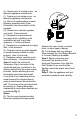
ROUND, SCONCE OR SQUARE HORIZONTAL TERMINATION CAP DECORATIVE CEILING SUPPORT/WALL THIMBLE COVER 2 PIECE WALL THIMBLE APPLIANCE ADAPTOR PIPE SECTION Figure 1 ROUND, SCONCE OR SQUARE HORIZONTAL TERMINATION CAP DECORATIVE CEILING SUPPORT/WALL THIMBLE COVER 2 PIECE WALL THIMBLE 90° ELBOW PIPE SECTION PIPE SECTION APPLIANCE ADAPTOR Figure 2 22 Supplemental Canadian Instructions When installing DirectVent Pro on appliances in Canada, a 2-piece Wall Thimble is required in order to comply with IR #41 (Fig
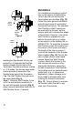
VERTICAL HIGH WIND OR LOW PROFILE TERMINATION CAP STORM COLLAR ROOF FLASHING CEILING FIRESTOP ROUND CEILING SUPPORT/WALL THIMBLE COVER CATHEDRAL CEILING SUPPORT BOX PIPE SECTION PIPE SECTION APPLIANCE ADAPTOR Figure 3 23
M&G DuraVent limited lifetime Warranty M&G DuraVent, Inc. (“DuraVent”) provides this limited lifetime warranty for all of its products with the exception of Ventinox® (lifetime), and PolyPro® (ten years). Subject to the limitations set forth below, DuraVent warrants that its products will be free from defects in material or manufacturing, if properly installed, maintained and used. DuraVent products are fully warranted if installed only by a professional installer.