Model: DURACELL POWER CENTER 5 kW INSTALLATION & STARTUP MANUAL
IMPORTANT SAFETY INSTRUCTIONS SAVE THESE INSTRUCTIONS This manual contains important instructions for the DURACELL POWER CENTER 5 kW, including the Power Control System (PCS) and base model battery cabinet installation and operation, herein defined as the ESS. The ESS is expandable with the addition of up to two more battery cabinets. Refer to this manual in Appendix A for more details if your system contains additional battery capacity beyond the base model.
TABLE OF CONTENTS 1 SAFETY ............................................................................................................................... 1 1.1 IN CASE OF EMERGENCY ................................................................................................................... 1 1.2 BATTERY MODULE SAFETY PRECAUTIONS ................................................................................................. 1 1.3 GENERAL SAFETY PRECAUTIONS ...........................................
13 SPECIFICATIONS ................................................................................................................ 25 Table 1: PCS Electrical / Mechanical Ratings .................................................................................25 Table 2: PCS Field Wiring Ratings – AWG / Torque ......................................................................... 26 Table 3: Battery Cabinet Electrical / Mechanical Ratings ...............................................................
1 Safety This manual contains important instructions for the DURACELL POWER CENTER 5 kW. The components described by this manual are intended to be used as part of an energy storage system and installed per all local building codes and regulations in addition to the National Electrical Code, ANSI/NFPA 70 (for US) and Canadian Electrical Code (for Canada).
1.3 General safety precautions Important! Installation, service, and operating personnel must read this document in its entirety, and observe all safety and installation procedures as described in this manual. Never operate system in a manner not described by this manual. Only qualified personnel should service this product. Ensure all covers are securely fastened after installation is complete.
2 Introduction 2.1 About this Manual – Target Audience This manual is intended to be used by qualified service and installation personnel for the purposes of product installation. This manual contains instructions for the installation and start up sequence of the DURACELL POWER CENTER 5 kW; including the PCS and battery cabinets. This product is permanently wired to the home electrical service, and must be installed by a licensed electrician only.
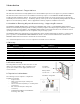
2.6 Initial Inspection of Material List – top level system components The system components supplied with your DURACELL POWER CENTER 5 kW are shown below. Each component should be inspected visually for any damage that may have been caused by shipment. If damage is present, please contact your local distributor.
2.6.1 Install kit – mechanical parts and manuals Item Qty DURACELL P/N Description Battery Cabinet 1 1 D-14kWh-LFP kit Incl. cabinet coupler assembly, two levelling brackets, and two plugs 2 1 Breaker Assembly DC breaker assembly 3 8 801003794 Adhesive backed battery module pads 4 1 801003757 Battery rack partition bracket (includes attached battery retaining clip 801003044) PCS Cabinet 5 1 D-5 kW kit Incl.
2.6.
3 Installation Site Preparation Before installing the product, read all instructions and warnings in this manual. CAUTION! All electrical installation work should be performed in accordance with local building and electrical codes. WARNING! Isolate the PCS from all energy sources prior to electrical installation by means of disconnects, breakers or connectors. Failure to properly isolate either AC or DC sources may result in serious injury or death.
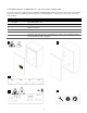
4 PCS and Battery Cabinet Wall-Mounting Instructions 1. Mount the wall bracket to the wall. Use the available slot pattern to mount to a load-bearing structure rated for the weight of the final system. The slots accommodate a M8 (5/16”) bolt diameter. IMPORTANT! Wall-stud mounting: A minimum of three wall studs spanned within the width of the mounting bracket are required. A minimum of two mounting bolts are required per stud (top/bottom). 2.
7. Remove the PCS cabinet from its packaging and stand upright. (not shown). Remove the front cover. 8. Assemble and mount the single lower-center leveling bracket as shown in steps 3 and 4 above. D-5kW 10 CAUTION! The PCS cabinet is heavy. Mechanical lift or two persons recommended. 9. D-14kWh-LFP Lift the PCS cabinet onto the wall mounting bracket. 10. Slide the PCS cabinet to the left such that it aligns with the alignment tab on the mounting bracket. 11.
5 Battery Module Assembly The following instructions include: • • Preparation and assembly of the battery cabinet modules and internal wiring. Interconnection of the PCS DC and communication cables to the battery cabinet. 1 Note: Overcurrent protection of the DC source is provided internally as part of the integrated battery system. No external DC disconnect is required. 5.1 Battery cabinet ground bus CAUTION! A torque wrench is required to ensure the power cables are terminated to their specifications.
5.3 Preparing battery modules for installation The PCS cabinet is not shown in the following steps. CAUTION! Ensure the battery module power switches are in the OFF position throughout the following procedure. Note: Observe the rotation of the modules on the lower and upper racks. The lower rack is rotated such that the chassis ground terminal is at the bottom of the module, while the upper rack chassis ground terminal is at the top. upper rack 1. (not shown) Remove a battery from its packaging.
5.4 Mounting and grounding the battery modules in the battery cabinet 1. Slide the lower rack battery into the cabinet as shown, and connect the ground cable to the ring terminal ground connector on the battery module as shown. 2. Push the module inward until making contact with the rear face of the cabinet. 3. Repeat steps 1 and 2 above with the 2nd lower rack module. 4. Mount the lower rack retaining clip. 5. Install the battery rack partition bracket as shown using the two M5 keps nuts provided.
5.5 Wiring the battery modules Follow the battery module power and communication jumper wiring below. Ref P/N A1 #3790 A2 #3793 B1 #3789 B2 #3796 C1 #3792 C2 #3794 Description DC- module jumper BLK 180 mm DC- module jumper BLK 400 mm DC+ module jumper RED 180 mm DC+ breaker cable RED 400 mm BMS jumper short 210 mm BMS jumper long 700 mm Pylon p/n label WI0BSC1000B2 WI0CUS300004 WI0BSC100001 WI0CUS300001 WI0SRJ458025 WI0SUS300002 5.5.
5.5.3 PCS to BMS communication cable This cable is specific to the battery model. Refer to the instruction that applies only to the battery module suppled. 1. Terminate the PCS – BMS / Console Y cable jumper in the [A/CAN] and [Console] ports of battery #1. This battery is herein referred to as the “Master” battery module. All other modules sync to the master. 2. Route the other end of the cable through the PCS port hole and terminate in the cable in the [BMS OUT] port as shown in figure 11.
5.6 DC- battery module to cabinet DC- connections Note: This is a continuation from section 5.2. The cables referenced A3 should already be terminated at the cabinet DC- terminal. Ref P/N A3 #3798 Description DC- terminal jumper BLK 400 mm Pylon p/n label WI0CUS300002 1. Connect the DC- power cables referenced A3 to the DCterminals of batteries 1 and 4 as shown.
5.7 PCS DC+ power and breaker assembly wiring Ref P/N B2 #3796 B3 #3797 P+ #2923 1. Description DC+ breaker cable RED 400 mm DC+ breaker cable RED 780 mm PCS DC+ power cable Pylon p/n label WI0CUS300001 WI0PUS300001 - Route the PCS DC+ power cable from the PCS through the cabinet coupling port. 2. Terminate the PCS DC+ cable, referenced [P+], at the top right busbar terminal of the DC breaker as shown. Torque to 15 in/lbs. 3.
6 System Electrical Wiring PCS cabinet – bottom view Note: This product is capable of providing utility interactive and islanded back up power, and can be AC coupled to a utility interactive photovoltaic inverter. Wiring methods must be in accordance with local electrical codes.
6.2 Chassis Grounding In this section, “Chassis Ground” is referred to as “ground” or “grounding” unless otherwise mentioned. The AC and DC grounding are intended to provide a low impedance signal path at all frequencies. DC Ground Wiring Installation: The PCS cabinet is shipped with ungrounded DC power terminals within the inverter. However, the default setting for DC grounding is set for DC negative to ground.
7 Battery module BMS definitions and operating states US3000C BMS power switch Powers the BMS only. DC bus not energized Startup button Press / hold 0.5s to energize the DC bus. Use the startup button on the master battery module only. Battery state of charge indicator Alarm indicator Master battery position indicated in figure 11. Run status indicator Figure 18: Pylontech US3000C BMS face plate. Condition Power ON RUN ALM SOC. Each LED represents 16.
8 ESS startup procedure 1 US3000C CAUTION! Powering the ESS requires a specific start-up procedure. Please follow the steps below. CAUTION! If the battery disconnect has been placed in the OFF position at any time during operation, wait one minute before returning to the ON position. Rapid cycling (less than one minute) of the battery disconnect can cause damage to the pre-charge circuit.
9 PCS Display Panel PCS Operating Mode Battery SOC 9.1 LED Display Indicators Service Mode Service button The PCS cabinet is equipped with a display panel that provides indication of the following: • Battery Operating State • PCS Operating State • (out of) Service Indicator Refer to section 9.2 for a complete definition of indicator states. To conserve energy, the LEDs will turn off after 5 minutes from being activated. They can be reactivated by pressing the service button.
9.4 Backup Power Operation This system will provide backup power to dedicated electrical circuits within the home via a permanently wired electrical sub-panel, referred to as the backup panel. Backup power is limited in rating and duration, both of which are dependent on the nature of the loads connected to the system, and the availability of the solar PV supply. This system is designed to reliably provide power to a refrigerator, home lighting, home electronics, and small appliances.
NOTE: If necessary, the load circuits can be shut off inside the backup panel to increase the battery charge rate. Do not shut off the PV circuit. 10 Maintenance This is a maintenance free product. Regularly scheduled inspection of the airflow path for the active cooling fans on the bottom side of the PCS cabinet is all that is required. This inspection should occur on an annual basis, or coincide with PV inspection.
12 Troubleshooting System faults are reported and logged in the monitoring system. All fault logs are also accessible remotely by your installer. IMPORTANT! Contact a DURACELL POWER CENTER 5 kW service representative as recommended below only after any of the following conditions are present on the front display of the inverter panel, and the recommended actions do not resolve the issue. Condition Definition Service light ON in grid mode System is prevented from normal operation due to internal fault.
13 Specifications Table 1: PCS Electrical / Mechanical Ratings Model Mode Maximum DC Voltage Operating DC Voltage Range Operating DC Voltage Range at 100% Output Power Maximum DC Current AC Power Factor* Operating Voltage Range (default) Operating Voltage Range (with ride-through) Operating Frequency Range (default) Operating Frequency Range (with ride-through) Number of Phases Nominal Output Voltage* Normal Output Frequency* Maximum Continuous Output Current D-5 kW Grid : Discharging Off Grid 80 V DC 40 t
Refer to section 13.1 for operating characteristics in compliance with the UL 1741 SA standard. Table 2: PCS Field Wiring Ratings – AWG / Torque Field Wiring Terminal Use Copper Wire Only, 90°C or higher rated Minimum Wire Size mm2 (AWG) Maximum Wire Size mm2 (AWG) Tightening Torque, Nm (in. lbs) 16 mm2 (6 AWG) 16 mm2 (6 AWG) 5.
13.1 UL 1741 SA Grid Support Utility Interactive Inverter Specifications The PCS within this integrated storage product complies with the UL 1741 SA standard for grid support utility interactive inverters. These functions are intended to be either enabled or disabled in accordance with local utility interconnection requirements. Table 5: UL1741 SA grid support functions.
Parameter Value for Rule 21 Value for Rule 14H Nominal AC voltage [V] 120 AC voltage accuracy [%Vnom or V] 1%, 1.2V Voltage trip time accuracy [s] 0.043 Minimum under-voltage [%Vnom] 50.0% Maximum over-voltage [%Vnom] 120.0% Default function status Enabled Enabled Table 8: SA10 Low and high frequency ride through settings.
Table 9: SA11 Ramp rate settings. SA11 Ramp Rates Parameter Value for Rule 21 Value for Rule 14H Output current rating for function [A] 20.8 Minimum normal ramp up rate [%Irated/sec] 1.0% Maximum normal ramp up rate [%Irated/sec] 100.0% Minimum output current [A] 0 Ramp rate accuracy [%Irated/sec] N/A Minimum soft start ramp up rate [%Irated/sec] 0.1% Maximum soft start ramp up rate [%Irated/sec] 100.0% Default normal ramp up rate [%Irated/sec] 100.0% 100.
Table 11: SA13 Volt VAR Mode SA13 Volt-VAr Mode Parameter Value for Rule 21 Value for Rule 14H Apparent power rating for function [VA] 5000 Output power rating for function [W] 5000 EUT input voltage range with function enabled [V] 40.0 - 80.0 Nominal AC EPS voltage [V] 120 AC EPS voltage range with function enabled [V] 96.0 - 144.
Table 12: SA14 Frequency-Watt settings. SA14 Frequency Watt Parameter Output power rating for function [W] AC frequency range with function enabled [Hz] AC frequency measurement accuracy [Hz] P(f) accuracy [%Prated or W] Value for Rule 21 Value for Rule 14H 5000 50.0 - 66.0 0.
13.2 Thermal performance: Charge / Discharge Curves Figure 21: Energy storage system thermal derated charge and discharge curves with base battery cabinet including four Pylontech US3000C modules.
Appendix A: Battery Expansion Cabinet Installation – batteries #5 to #8 The DURACELL POWER CENTER 5 kW system supports up to two additional expansion cabinets. Where duplicated, the mechanical assembly and wiring instructions will be referenced to previous sections within this document. All instructions specific to the first expansion cabinet are documented below, with battery modules numbered 5 to 8 inclusively. Startup and operation, section 8, remains unchanged. A.
2.6.
A.2 Wall bracket installation The expansion cabinet is included with a wall bracket extension that is secured to the base system’s bracket. 1. base Align the expansion bracket to the base bracket and secure with the mounting hardware provided. expansion 2. IMPORTANT! Secure the bracket to the wall using a minimum of four 5/16” lag bolts in atleast two wall studs. A.3 Mounting the cabinet to the wall 1. 2.
Appendix B: Electrical Block Diagram – Internal The following table / diagram defines the internal electrical wiring of the DURACELL POWER CENTER 5 kW, including the base and two additional expansion battery cabinets. The diagram is for illustrative purposes, and does not reflect the actual physical orientation of the battery modules within the cabinets.
INSTALLATION NOTES
Doc-93005