
Install Manual

9
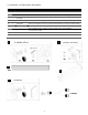
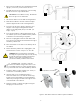
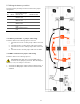
7. Remove the PCS cabinet from its packaging and stand
upright. (not shown). Remove the front cover.
8. Assemble and mount the single lower-center leveling
bracket as shown in steps 3 and 4 above.
CAUTION! The PCS cabinet is heavy. Mechanical
lift or two persons recommended.
9. Lift the PCS cabinet onto the wall mounting bracket.
10. Slide the PCS cabinet to the left such that it aligns
with the alignment tab on the mounting bracket.
11. From the rear side of the cabinet, adjust the outer
wingnut on the single levelling bracket until the
cabinet is vertically plumb (level) to the wall. (see
image – step 6).
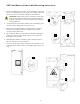
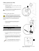
12. Insert the PCS cabinet coupling gasket between the
two cabinets (lower-front). Slide the battery cabinet
towards the left until mating to the gasket.
13. Place the coupling plate inside the PCS cabinet and
insert the four mounting bolts and washers through to
the battery cabinet side.
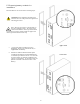
14. Place star washers on the bolts on the battery side of
the cabinet.
15. Mount the battery cabinet side coupling plate, and
fasten with the lock nuts. Torque to 10 – 15 in-lbs.
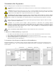
WARNING! The mounting bolts of the flange
assembly are required to be fully secured, as they
provide the chassis grounding for the battery
cabinet. Torque nuts as specified in the
specification tables provided in this manual.
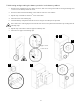
16. Continuity test: Check the continuity
between the cabinets using an Ohm meter. The
test reading must be zero Ohms at a bare metal
point inside each of the PCS and battery cabinets.
17. Install the cabinet coupler end plate (see- LP kit) to
seal the hole on the battery cabinet.
18. Optional: (This is not a load bearing anchor –
anchored conduit runs to the PCS are satisfactory).
Install screws in leveling plates for PCS and battery
cabinets by inserting a screwdriver through the hole
on the backside of the cabinets.
19. Plug hole on back of cabinet using by inserting the
hole plug from the front side.
10
Optional (
hardware
not included)
12
16
thru
18
19
X4
17
D
-
5kW
D
-
14kWh
-
LFP
D
-
5kW
D
-
14kWh
-
LFP
Figure 6: PCS cabinet and inter-cabinet coupler installation.