
Install Manual

10
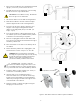
5 Battery Module Assembly
The following instructions include:
• Preparation and assembly of the battery cabinet modules
and internal wiring.
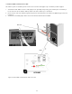
• Interconnection of the PCS DC and communication cables
to the battery cabinet.
Note: Overcurrent protection of the DC source is provided
internally as part of the integrated battery system. No
external DC disconnect is required.
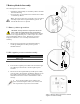
5.1 Battery cabinet ground bus
CAUTION! A torque wrench is required to ensure the
power cables are terminated to their specifications.
Over-torque can damage the DC breaker and/or strip the
threads on the copper bus bar posts. Under-torque can result in
an arc fault hazard, and risk of fire. Damage as a result of
improper termination is not covered by the manufacturer
warranty.
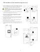
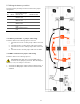
1. Mount the four ground wires provided in the battery
module grounding kit into the 4-position ground
distribution block.
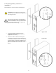
5.2 DC negative power terminal assembly
2. Route the DC negative power cable from the PCS through
the cabinet port and mount to the DC negative power
terminal.
3. Mount the two DC negative battery module power cables,
referenced A3, (as provided in the battery cable kit) to the
DC negative power terminal. Offset each power lug so
that a flush electrical contact is made between each of
the lugs.
4. Secure the DC negative power cables to the
power terminal using the washer, lock washer, and
hex nut provided. Torque the nut to 35 in/lbs.
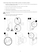
Ref
P/N
Description
Pylon p/n label
A3 #3798
DC
-
terminal jumper
BLK 400 mm
WI0CUS300002
P- #2925 PCS DC- power cable -
3/8”
A3
A3
1
4
2
3
3
Figure
7
: Battery cabinet ground wire and DC
negative terminal assembly.