
Install Manual

14
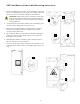
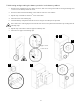
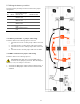
5.5.3 PCS to BMS communication cable
This cable is specific to the battery model. Refer to the instruction that applies only to the battery module suppled.
1. Terminate the PCS – BMS / Console Y cable jumper in the [A/CAN] and [Console] ports of battery #1. This battery is
herein referred to as the “Master” battery module. All other modules sync to the master.
2. Route the other end of the cable through the PCS port hole and terminate in the cable in the [BMS OUT] port as shown
in figure 11.
3. Terminate the two BMS jumper cables referenced C1 between batteries #1-2 and #3-4.
BMS OUT
1
US3000C
#3810
Fi
gure
11
: PCS to BMS communication cable connection.