
Install Manual

17
6 System Electrical Wiring
Note: This product is capable of providing utility interactive and
islanded back up power, and can be AC coupled to a utility interactive
photovoltaic inverter. Wiring methods must be in accordance with
local electrical codes. The installer is responsible for ensuring that over-
current protection is installed and sized appropriately for the AC grid
and off-grid output circuits, in accordance with the National Electrical
Code, ANSI/NFPA 70, Canadian Electrical Code and local codes.
All field wiring connections to the battery system are at the PCS cabinet only.
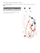
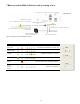
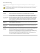
Figure 14 indicates the knockout locations for conduit entry into the PCS,
categorized as AC power and signal level circuits.
IMPORTANT! Drilling holes anywhere in the battery or PCS cabinet
renders the warranty null and void. Use the knockouts provided at the
bottom face of the PCS cabinet only! Do not drill holes anywhere in the
battery system. Use conduit fitting reducers, if applicable.
6.1 AC power connections
This battery system contains two independent AC power connection ports; one port
dedicated for an electrical utility connection, marked “AC Grid”, the other port
dedicated for backup operation, marked “AC Load”. This product’s primary
application is intended for utility interconnection, and must be connected to a
utility electrical service supplying split phase 240/120 Vac, 60 Hz. The backup
operation of this product is a secondary application, and is intended to supply
emergency backup operation only.
Note: The PCS provides galvanic separation between AC and DC Sources.
CAUTION! To reduce the risk of fire, connect only to a dedicated circuit
provided with appropriate branch circuit over-current protection in
accordance with local electrical codes.
WARNING! Improper connection of the wiring panel may result in
equipment damage and cause personal injury. Disconnect all AC and DC
Sources prior to installation.
CAUTION! The AC grid and load ports are independent circuits, controlled
internally by an automatic bypass and transfer switch. Each port must be
connected to electrically isolated panels. Do not tap line or neutral wires
from the main electrical panel to the backup panel, as this may result in
permanent damage to the product.
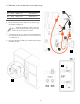
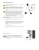
AC Grid Port:
1. Open the spring clamp terminals on the AC circuit board at the port
marked “AC Grid”.
2. Terminate the AC grid connection wires as follows: “L_Grid” = Line,
“N_Grid” = Neutral, and “PE” = Ground.
3. Close the spring clamp terminals, ensuring levers are fully engaged.
AC Load Port:
1. Open the spring clamp terminals on the AC circuit board at the port
marked “AC Load”.
2. Terminate the wires at “L_AC load” (Line), “N_AC load” (neutral), and
“PE_AC load” (protective earth).
3. Close the spring clamp terminals, ensuring levers are fully engaged.
PCS cabinet – bottom view
AC power
Signal
Figure 14: PCS knockout detail.