
Install Manual

18
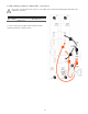
6.2 Chassis Grounding
In this section, “Chassis Ground” is referred to as “ground” or “grounding” unless otherwise mentioned.
The AC and DC grounding are intended to provide a low impedance signal path at all frequencies.
DC Ground Wiring Installation: The PCS cabinet is shipped with ungrounded DC power terminals within the inverter.
However, the default setting for DC grounding is set for DC negative to ground. This is to indicate that the DC negative
terminal of the inverter is grounded within the PCS system. The DC negative ground is completed once terminated in the
master battery cabinet.
AC Ground Wiring Installation: The AC power grounding is achieved through the PE terminals of the AC grid connectors on
the AC Filter Board, as shown in section 6.1.
Note: The field ground wire rating applies to the AC circuit only. The DC source loop is internal to the battery
cabinet, and is rated accordingly.
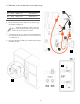
Lightning Grounding: The inverter has built-in lightning protection. In order for the lightning protection to be effective, the
grounding for lightning currents must be provided via low impedance path from AC Filter Board to System Ground and
further to the building Ground/Earthing point.
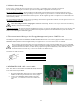
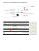
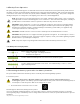
6.3 Communication Wiring to the Energy Management System – RJ45 Pin-out
The EMS panel supplied with the DURACELL POWER CENTER 5 kW includes a 10 ft factory prepared cable. Refer to the
DURACELL HUB installation manual supplied with your equipment for connection instructions to the EMS.
Note: The ESS communicates with the energy management system using the Modbus protocol over an RS-485
network. Shielded twisted pair cable is required. Should the installation require further separation between the
EMS panel and the PCS cabinet, a cable can be prepared using CAT 5 shielded wire, with an RJ-45 connector
terminated at the PCS end only. Connect the shield to the EMS end only.
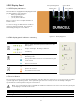
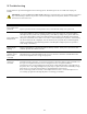
Terminate the cable as shown:
EMS
PCS
PCS:
RJ
-
45 Pin
G
+shield
G
3
A
A
4
B
B
5
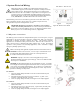
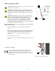
6.4 DURACELL HUB - AK1 control cable
Note: This cable is included with the DURACELL HUB, identified
in the material list as p/n #3653.
1. Plug in the #3653 AK1 cable harness from the DURACELL
HUB to the AK1 relay terminal bock as shown (right).
2. Refer to the DURACELL HUB installation manual,
section 4.2, for termination instructions within the
Hub.
1