
Install Manual


35
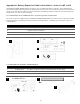
A.2 Wall bracket installation
The expansion cabinet is included with a wall
bracket extension that is secured to the base
system’s bracket.
1. Align the expansion bracket to the base
bracket and secure with the mounting
hardware provided.
2. IMPORTANT! Secure the bracket to
the wall using a minimum of four
5/16” lag bolts in atleast two wall
studs.
A.3 Mounting the cabinet to the wall
1. Remove the cabinet coupling end plate from the lower right side of the base battery cabinet and install it on the lower
right port hole of the expansion cabinet.
2. Follow the cabinet installation instructions in section 4 to secure the cabinet to the wall.
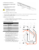
A.4 Battery module assembly
1. Follow the assembly instructions in section 5.2 through 5.4.
2. See section 5.5 (figure 12) – remove the lower DC- cable (referenced A3) from the DC- terminal, and replace with
the cable referenced A5 in figure 25 below.
A.5 Battery module wiring
1. Connect the internal power and communication
jumper cables as shown in sections 5.5.1 and
5.5.2. Note the relative position of batteries 5
thru 8 as they mirror batteries 1 thru 4.
2. Route the DC power cables, referenced A4 and
B4, through the coupling port and terminate
them at battery #8.
3. Remove the DC+ breaker assembly.
4. Remove the DC+ cable referenced B3 (section
5.6, figure 12) and replace with the cable
referenced B5 (shown right). Torque to 15 in-lbs.
5. Mount the DC+ breaker assembly.
6. Route the BMS jumper cable referenced C3
through the cabinet coupling port and terminate
at the link port terminals at battery #4 and #5.
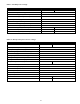
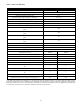
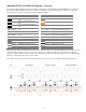
Ref
P/N
Description
Pylon p/n
A4 #3801
DC
-
jumper cable
BLK 1100 mm
WI0CUS300008
A5 #3802
DC
-
terminal
cable BLK 1200
mm
WI0CUS300006
B4 #3800
DC+ jumper cable
RED 1100 mm
WI0CUS300007
B5 #3799
DC+ breaker cable
RED 1200 mm
WI0CUS300005
C3 #3795
BMS jumper
cable
1500 mm
WI0SRJ45815M
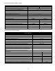
base
expansion