
Install Manual


36
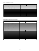
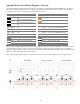
Appendix B: Electrical Block Diagram – Internal
The following table / diagram defines the internal electrical wiring of the DURACELL POWER CENTER 5 kW, including the
base and two additional expansion battery cabinets. The diagram is for illustrative purposes, and does not reflect the
actual physical orientation of the battery modules within the cabinets.
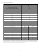
Note: DC power cables marked by an asterisk (*) in the table above indicate required modifications to the cable set used
in the base battery cabinet. Only one set of “home run” DC power cables is used per complete system. For example:
adding one expansion battery cabinet requires the replacement of [A3] / [B3] with [A5] / [B5] “home run” cables, and the
addition of [A4] / [B4] “daisy chain” jumper cables.
Note: Battery module ground cables are one per battery, with a “home run” to the cabinet chassis ground terminal.
Ref
P/N
Description
Ref
P/N
Description
A1 #3790
DC
-
module jumper BLK 180
mm
B1 #3789 DC+ module jumper RED 180 mm
A2 #3793
DC
-
module jumper BLK 400
mm
B2 #3796 DC+ breaker cable RED 400 mm
A3 #3798
DC
-
terminal jumper BLK 400
mm
A3* #3798
DC
-
terminal jumper BLK 400
mm
B3* #3797 DC+ breaker cable RED 780 mm
A4* #3801 DC- jumper cable BLK 1100 mm
B4* #3800 DC+ jumper cable RED 1100 mm
A5* #3802
DC
-
terminal cable BLK 1200
mm
B5* #3799 DC+ breaker cable RED 1200 mm
A6* TBD
B6* TBD
C1 #3792 BMS jumper short 210 mm
D1 #3810 PCS-BMS “Y” CAN/Console 3000C
C2 #3794 BMS jumper long 700 mm
P- #2925 PCS DC- power cable
C3 #3795 BMS jumper cable 1500 mm
P+ #2923 PCS DC+ power cable