
Install Manual


3
2 Introduction
2.1 About this Manual – Target Audience
This manual is intended to be used by qualified service and installation personnel for the purposes of product installation.
This manual contains instructions for the installation and start up sequence of the DURACELL POWER CENTER 5 kW;
including the PCS and battery cabinets. This product is permanently wired to the home electrical service, and must be
installed by a licensed electrician only. The battery capacity of this system can be expanded by adding additional cabinets
adjacent to the base battery cabinet. Refer to Appendix A for battery expansion installation instructions.
2.2 Installation Planning & System Commissioning - Supporting Documents
The DURACELL POWER CENTER 5 kW is operated by the DURACELL HUB. Please consult DURACELL HUB Installation
Manual for full installation planning details, including conduit layout plans and sample single line diagrams for a complete
solar plus storage system installation. The DURACELL HUB installation manual also describes in more detail the various
operating modes and configurations for AC coupled PV solar plus storage systems.
The DURACELL HUB energy management system & gateway requires installer administration and device commissioning
prior to operation of the DURACELL POWER CENTER 5 kW. Refer to the Fleet Installer Administration Guide and the
DURACELL HUB Install and Commission Quick Guide for further details.
Go to
www.duracellpowercenter.com
for a complete list of installer resource materials.
2.3 Glossary
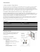
2.4 Product markings
The ratings label is located on the bottom face of each
cabinet. The serial number / date code labels for the
system are located as shown (right) with the front
covers removed.
2.5 Special tools & hardware
The following tools are required to complete the
installation of the ESS:
• Torque wrench
• 17mm socket wrench (DC- main power
connection).
• 10mm socket wrench (battery +/- module power
connections).
• 3/8” socket wrench (DC+ main power
connection).
•
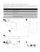
Load bearing hardware for wall bracket
mounting. 5/16” (M8)
Term Definition Term Definition
AC Alternating Current LED Light Emitting Diode
ARC Auto Recovery Circuit NC / NO Normally Closed / Normally Open
CPU Central Processing Unit PCS Power Control System (Inverter)
DC Direct Current PE Protective Earth
EMS Energy Management System PV Photo-Voltaic
ESD Electrostatic Discharge RF Radio Frequency
ESS Energy Storage System SOC State Of Charge (Battery)
GND Ground SOH State of Health (Battery)
All cabinets: ratings label
PCS
cabinet:
s/n, date code
Battery cabinet:
s/n, date code