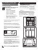
Storage Shed OWNER’S MANUAL / Instructions for Assembly Patent #416.091 Size 10’x 8’ with “Extension Kits” Ver: 2.0 Customer Service Hotline (800) 483-4674 www.uspolymersinc.com Your Total Solution To maintenance Free Storage Sheds. • All Weather Durable PVC • Won’t Dent, Rust, Rot or Mildew • Tall Walk In Shed • Never Needs Painting • 61” Wide Double Doors • Easy Assembly • High Wind Tested • Snow Load Tested 20lbs/sq.
Duramax Storage Shed Limited Fifteen Year Warranty U.S. Polymer Inc. will send a replacement part free of charge, in the event of material defects and or workmanship for a period of fifteen years from the date of purchase. This warranty is extended only to the original purchaser. A purchase receipt or other proof of date of original purchase will be required before warranty service is rendered. In no event shall we pay the cost of flooring, labor, installation or any other costs related thereto.
10’ x 8’ Parts List Note: Check all parts prior to installation.
10’ x 8’ Exploded View FPL RS10A FPR RS7XA RS2A RS3XA RS6XA RS11A RS2A MJ RS4XA RS4XA RS4XA RS3XA RS4XA MJ RS3LA RS5A RS12A RS3LA RS2A RS5A RS1A RS2A DSH RS10A RS8A RS1A RS9A FPR MJ FPL CB3XA MJ MJ CB3XA MJ CB3XA CB3XA
One Extension Parts List Note: Check all parts prior to installation.
Exploded View with One Extension RS11A RS13A RS7A RS4A RS13A RS6A RS3SA RS4A RS12A RS13A RS13A EXTR EXTL RS3SA
A. Foundation & Base Frame PART 1: Assembling Shed With Extension Kit Note: It is important that these instructions are followed step by step. Wooden Platform (Not Included) The following are a list of lumber and sizes you will need. DuraMax must be installed on a level wooden platform or a level concrete foundation. platform is extra and is not included. Note Wooden Don’t install under windy conditions. Pressure Treated-Wood Studs: Exterior Grade (CDX): 6ea 2”x 4”x 89” (50 x 88.9x 2260.
4. Using a carpenters square, line up all corners. Secure base to wood foundation using (S1) screws. B3RA Concrete foundation 4b. Shed or shed foundation should be placed on concrete footing by use of anchor bolt and nut. Using a carpenters square, line up corners. Align U-Channel base, mark the concrete through the holes in the base and drill concrete with 1/2” (dia. 12.5mm) concrete bit to accept anchor bolts to a 1 3/4” (44mm) depth.
2. Insert the side panel (SP ) into the groove of column (CDRA). Start at the bottom of the panel at an angle then push into place. Note Note Always place panels into frame at an angle on top and slide in sideways and downward for easy insertion. CDRA Make sure panels are right side up with panel shingles facing down. Check the stamped label on top of all panels. CDRA B1RA Inside 3. Slide corner column (CCA) into side panel (SP ) pushing the column to the side panel. CCA CCA Inside 4.
5. To stabilize the front panel attach center band (CB1A). Start with center band fitting (FCB), fix to corner column (CCA) with (S2) screws. See figures (fig.1) (fig.2) and (fig.3). 1& 2 CB1A 3 CB1A CCA S1 S1 CDRA CDRA CCA FCB FCB CB1A S2 CB1A CCA Fig.1: Use (S2) screws. Fix (FCB) fitting to (CCA). Leave it loose. Fig.3: Use Fig.2: Use (S1) screws. Fix (CB1A) to fitting (FCB) Inside (S1) screw. Fix (CB1A) to (CDRA) 6.
7. Assemble the center bands (CB3XA) & (CB3XA) with middle joining support (MJ). use (S1) screws. See fig. CB3XA CB3XA S1 MJ CB2A MJ CB3XA 8. Assemble the center bands (CB3XA) & (CB3A) with (S3) screws CB3XA with nuts. Follow Overlapping Method shown below. Make 2 sets. Add one (CB3A) for each extension. CB3A CB3XA S3 CB3A Overlapping Method For Center Band & Roof structure (RS3). TIP Step 1 Use a hammer to align the holes.
9. Working from inside continue connecting the side panels (SP ) and columns (CMA) in sequence along (B22 & B21) & (EXTR) base. Use (S1) screws to fix columns to base. 9a. For each extension add one side panel (SP ) and one column (CMA) in extension base U-channel (EXTR) & (EXTL). CMA CMA CMA CMA S1 EXTR B21 B22 Inside B3RA 10. Slide corner column (CCA) into side panel (SP ) pushing the column to the side panel. CCA CCA EXTR B3RA Inside 11.
12. Stabilize the side panels with center bands (CB3XA) & (CB3A). Fix (FCB) fitting to corner column (CCA). See Fig.1 Follow the Fig. 2, 3, 4, 5 & 6. CB3XA CB3A CCA CCA S1 1&5 FCB CMA CMA CMA 6 4 3 2 CB3A FCB S2 CB3XA CB1A CB3XA CB1A CCA Fig.1: Use (S2) screws. Fix (FCB) fitting to (CCA). Leave it loose. CCA Fig.2: Use (S1) screws. Fix (CB3XA) to (FCB) and (CB1A) EXTR B3RA B21 B22 Inside CMA S1 CMA CB3XA FCB CB3A S1 S1 CCA Fig.3: Use (S1) screws.
13. Working from inside continue connecting the 4 back panels (SP ) and columns (CMA) in sequence along (B3RA) & (B3LA) base to corner column (CCA). Use (S1) screws to fix columns to base. Slide corner column (CCA) into side panel (SP ) pushing the column into position. See (fig.1) and (fig.2). CCA CCA CMA CMA CMA CMA CCA B22 B3LA S1 B3RA B3LA Inside back wall S1 CCA CCA 0utside fig. 2 CB3XA B3LA B22 CCA CB3XA fig. 1 1&5 CMA CMA CMA 3 4&6 3 CB3XA CCA 2 CB3XA 14.
. Working from inside continue connecting the side panels (SP ) and columns (CMA) in sequence along (EXTL) (B22 & B21) base. Use (S1) screws to fix columns to base. CMA CCA CMA CMA CMA S1 B22 B21 EXTL Inside 16. Slide corner column (CCA) into side panel (SP ) pushing the column to the panel. CCA CCA B1LA B21 Inside 17. Working outside Use (S1) screws to secure column to bases (B21) and (B1LA).
18. Stabilize the side panels with center bands (CB3XA) & (CB3A). Fix (FCB) fitting to corner column (CCA). See Fig.1 Follow the Fig. 2, 3, 4, 5 & 6. CB3A CB3XA S1 CCA CCA S2 6 4 3 CCA 2 CB3A CB1A CCA Fig.1: Use (S2) screws. Fix (FCB) fitting to (CCA). Leave it loose. CMA CB3XA CB3A CB3A CMA 1&5 FCB FCB CMA Fig.2: Use (S1) screws. Fix (CB3A) to (FCB) and (CB1A) EXTR B3RA B21 B22 Inside CMA S1 CMA CB3A CB3XA CB3A FCB CB3XA S1 S1 CCA Fig.3: Use (S1) screws.
19. Insert the side panel (SP ) into the groove of column (CCA). Start at the bottom with panel at an angle then push into place. CCA CCA B1LA Inside B1LA 20. Slide door column (CDLA) into the U-Channel CCA Base (B1LA) on the left side of the door. Line up the pre-drilled holes on (CDLA) Column with predrilled holes on U-Channel Base (B1LA). Fix with two (S1) screws from inside. (see blowup detail). CDLA CDLA B1LA S1 21. To stabilize the front panel attach center band B1LA (CB1A).
22. Fix center band (CB4A) to (CDLA) and Base (B1LA) See figures (fig.1), (fig.2) and (fig.3). CB4A CB1A 1&3 CB1A S1 CDLA S1 CDLA CB4A B1LA CB4A Fig.2: Use Fig.1: Use (S1) screw. Fix (CB4A) to base (B1LA) (S1) screw. Fix (CB4A) to (CDLA) B1LA Inside EPS CDLA CB1A EPS CB4A Fig.3: Fix the (EPS) at the end of (CB1A) & (CB4A). 23. Make sure the door opening between the door columns (CDLA) and (CDRA) is 61 1/4” (1556mm). This will ensure a perfect fit for the doors.
1. Insert the middle column fitting (FMC) into top FMC FMC of the middle columns (CMA). Fix the column to fittings with (S1) screws from inside the shed. FMC FMC FMC CMA FMC CMA CMA CMA CMA FMC FMC CMA FMC CMA S1 CMA Inside FMC Inside CMA CMA CMA 2. Insert the corner column fittings (FCC) into the FCC corner columns (CCA). Fix with (S1) screws from out side of the shed. FCC CCA FCC FCC CCA FCC CCA CCA CCA FCC CCA S1 CCA 3.
14 MJ RS3XA RS2A RS4XA RS1A RS3LA RS4XA RS6XA RS10A RS12A RS1A RS2A RS9A RS5A RS12A RS11A RS7XA RS8A RS10A RS1A RS11A RS2A MJ DSH RS4XA Roof Structure Exploded View RS5A MJ RS3XA RS4XA RS2A RS3LA RS1A
RS3SA 15 RS4A RS13A RS6A RS13A RS12A RS11A RS13A RS7A RS13A RS13A RS13A RS4A RS3SA RS13A Roof Structure Exploded View with One Extension RS13A
Front roof structure assembly 4. Assemble front roof structures (RS1A) 2 nos. and middle RS1A joining support (MJ) together with 4 (S1) screws. MJ MJ RS1A RS1A S1 RS1A U- 5. Assemble roof structure support (RS8A) and (RS9A) to (RS1A) assembly with only 6 (S1) screws as shown in fig. U- Ch an n O el pe nin Ch a nn O el pe nin g RS9A g RS8A RS1A RS8A U- Ch an l ne Op en ing RS9A S1 These holes up RS1A Step 1 6.
Back roof structure assembly 7. Assemble back roof structures (RS1A) 2 nos. and middle RS1A joining support (MJ) together with 4 (S1) screws. MJ MJ RS1A RS1A S1 RS1A U- 8. Assemble roof structure support (RS8A) and (RS9A) to (RS1A) assembly with 8 (S1) screws. U- Ch an n O el pe nin Ch n an O el pe nin U- Ch an Op en RS9A g RS8A RS1A RS8A l ne g ing S1 RS9A These holes up RS1A Step 1 9. Assemble roof structure (RS2A) to (RS8A) RS2A S1 and (RS9A) with 8 (S1) screws.
10. Assemble the roof structures (RS3LA), (RS3XA) 4&5 with middle joining support (MJ). Use only 2 (S1) screws as shown in fig. 1. Assemble (RS3XA) & extension roof structure (RS3SA) with 2 (S1) screws. See fig. 2 & 3. Make 2 sets. For each extension add one (RS3SA). 2&3 1 RS3SA RS3XA MJ S1 RS3XA 4&5 RS3LA MJ Refer Page No. 5 for Overlapping Method of (RS3XA) & (RS3SA). Note RS3LA fig.1 RS3SA RS3SA RS3XA S1 RS3XA fig.2 fig.3 10a.
11. Assemble the roof structure (RS6XA) into (RS5A) with 8 (S1) screws. Make 2 sets. RS6XA S1 RS5A S3 RS6A 12. Assemble the roof structure (RS6XA) into (RS6A) with 6 (S3) screws with nut. Make 2 sets. Add one roof structure (RS6A) for each extension. RS6XA RS5A S3 13. Assemble the roof structure into (RS5A) & (RS6A) into roof structure (RS13A) with 8 (S3) screws with nuts at both ends. Make 2 sets.
14. Assemble the roof structure (RS7XA) into (RS5A) with 8 (S1) screws. Make 2 sets. RS7XA RS5A S1 15. Assemble the roof structure (RS7XA) into (RS7A) with 6 (S3) screws with nut. Make 2 sets. Add one roof structure (RS7A) for each extension. RS7A RS7XA S3 RS5A 16. Assemble the roof structure (RS5A) & (RS7A) into roof structure (RS13A) with 8 (S3) screws with nuts at both ends. Make 2 sets.
17. Place the assembled front roof structure into position on top of door columns. Line up pre-drilled holes with door column fittings (FDCL) & (FDCR). Use (S1) screws to fix front roof structure to the door columns with left and right door column fittings. Inside of shed FDCR FDCL CDLA CDRA 18. Fix the door stopper horizontal (DSH) to the front roof structure from inside with 6 (S1) screws. Position the latch hole to face down. DSH U-channel opening inside the shed.
19. Place the assembled back roof structure into position on top of middle columns (CMA). Line up pre-drilled holes with middle column fittings (FMC). Use (S1) screws to fix back roof structure to (FMC). Inside back of shed FMC CMA S1 FMC FMC CMA CMA RS1A 2 RS1A Note Make sure the (RS2A) roof structure position towards inside the shed as shown in Fig.1 & 2. RS1A 1 RS1A RS2A RS2A RS2A 22 Fig.1 RS2A Fig.
20. Insert the 90 degree joint (RJ) (assembled with RS3LA, RS3XA & RS3SA) into (RS1A) see fig. 1 Follow fig. 2 & 3. Note RS3SA RS3XA After assembly make sure this roof structure’s U-Channel is positioned down. RS3LA 1,2&3 RS1A RS3SA Note Notice the U-channel up position on roof structures (RS1A). RS1A 1,2&3 RS3XA RS3LA RS3SA 1,2&3 RS3XA RS1A RS1A 1,2&3 RS1A RS3LA RS1A S1 RS2A RJ RS2A RST S2 RS3LA S1 RJ RS1A RJ FCC RS1A CCA CCA fig.3 fig.2 fig.
22. Place the assembled roof structure (RS5A) & (RS6A) into position on roof structure supports (RS8A) at the left side of the shed. Use (S1) screws to fix. See fig.1 & 2. RS6A RS6XA RS7A RS5A RS7XA RS5A 23. Place the assembled roof structure (RS5A) & (RS7A) into position on roof structure supports (RS8A) at the right side of the shed. Use (S1) screws to fix. See fig.1 & 2. 2 RS6A RS7A RS6XA RS7XA RS5A RS5A 1 RS13A RS13A RS2A RS2A RS5A RS5A RS8A S1 Front Inside fig.
24. Place the assembled roof structure (RS5A) & (RS6A) into position on roof structure supports (RS9A) at the left side of the shed. Use (S1) screws to fix. See Fig.1 & 2. RS6A RS6XA RS7A RS5A RS7XA RS5A 25. Place the assembled roof structure (RS5A) & (RS7A) into position on roof structure supports (RS9A) at the right side of the shed. Use (S1) screws to fix. See Fig.1 & 2. RS6A RS7A RS6XA RS7XA RS5A RS5A RS5A Inside Front 25 RS7A S1 RS9A fig.1 S1 Inside Back RS9A fig.
26. Attach the roof structures (RS4XA) 4 nos. to (RS3LA) and (RS3XA) with (S1) screws. See fig. 1 and 2. RS3XA 2 26a. Attach the roof structures (RS4XA) 4 nos. to (RS5A), (RS6A) assembly and (RS5A), (RS7A) assembly with (S7) screws. See fig. 3 and 4. RS7A RS6A RS4XA 4 3 RS4XA RS3LA 1 RS4XA 4 4 3 RS4XA 2 4 RS4XA 1 S1 S1 RS4XA RS7XA RS4XA RS7XA RS7A RS6XA RS4XA RS4XA RS4XA RS3XA RS5A RS3LA RS5A RS3LA fig.1 S7 fig.2 S7 fig.3 27. Attach the roof structures (RS4A) one fig.
28. Attach roof structure supports (RS10A) 3 and (RS11A) to roof structures (RS5A), (RS6A) & (RS7A) using (S1) screws. For each extension add one (RS11A). See (fig.1), (fig.2) and (fig.3). RS10A RS11A 2 RS11A 2 RS11A RS10A 2 RS11A RS10A 1 RS11A RS11A RS10A Note Make sure hole in (RS10A) face outward on both sides. RS10A RS13A RS13A RS5A RS11A RS6A RS7A RS5A RS10A RS8A RS8A RS8A S1 S1 S1 Inside Front fig.1 27 RS10A fig.2 Inside Back fig.
29. Attach the roof structure support (RS12A) with (RS5A) to (RS5A) and (RS6A) to (RS7A) with (S1) screws. See (fig.1) and (fig.2) Add one roof structure (RS12A) for each extension. RS12A RS6A RS7A RS12A RS12A RS5A RS12A RS5A RS4A RS4A RS5A RS12A S1 fig.1 28 RS5A RS12A S1 fig.
D. Roof panels Parts Needed: Parts Needed for each extension: (6) Roof Panels (2) Facia Panel Left (2) Facia Panel Right (3) Ridge Cover Small (80) Roof Plug w/Washer (80) Roof Pin (12) Sagging Support (RP ) (FPL) (FPR) (RRS) (PPG) (PIN) (RS14A) (2) Roof Panels (1) Ridge Cover Small (16) Roof Plug w/Washer (16) Roof Pin (4) Sagging Support (RP ) (RRS) (PPG) (PIN) (RS14A) Front FPR Fig.1 1. Place facia panel (FPR) to front roof structure right side. Front Front FPR FPL FPR 2.
RP RP Fig.3 Fig.2 RP Fig.5 Fig.4 Fig.6 Fig.7 RRS FPR Fig.8 30 Fig.
RRS RRS Fig.11 Fig.10 RRS Fig.12 5. Insert the sagging support (RS14A) from inside the shed by sliding in between roof structure (RS5) and roof panel until it reaches (RS3) roof structure for each panel. See fig.1. 6. Insert the sagging support (RS14A) from inside the shed by sliding in between roof structure (RS5) and roof panel until it touches the other roof structure (RS5). See fig.2. RS14A RS14A RS5 RS3 Outside View Inside View Fig. 1 31 Fig.
E. Doors Parts Needed: (1) Door Left (1) Door Right 1. Attach the doors left and right (see fig.1) with Loose pin hinges on door columns (CDLA) and (CDRA). fig.
Note: To prevent water leakage it is important that these instructions are followed. 1. After completing the assembly apply silicone around the perimeter of the base U-channel. Seal the corners, joints and base of door column also. 3 4 Inside Base U-channel 2. After completing the panel assembly, apply silicone around the roof plugs. This is optional and should be done for heavy rain areas if needed.
F. Optional Ventilation Kit ACCESSORIES CODE DESCRIPTION VC VCP VENTILATION COVER VENTILATION COVER PIN QTY 2 4 VENTILATION COVER (VC) VENTILATION COVER PIN (VCP) TOOLS YOU WILL NEED Power Drill Dia 5/32” (4.2mm) drill bit Dia 1/2” (12.5mm) drill bit VC Optional ventilation kits can be installed on any of the wall panels. However, we recomend mounting them on the top of the shed’s back wall. 1. Place the ventilation cover (VC) as shown in fig.1. Using a pencil, mark the two side hole locations.
High wind area installation instructions Note: To ensure that your shed withstands high winds, you will need the following reinforcement. Parts needed: CODE DESCRIPTION S4 DIA. 4.2 x 16mm. (5/32” x 5/8”) SHEET METAL SCREW M6 x 40mm. (1/4” x 1 1/2”) Anchor bolt with nut S5 Parts needed for each extension: QTY CODE DESCRIPTION S4 DIA. 4.2 x 16mm. (5/32” x 5/8”) SHEET METAL SCREW M6 x 40mm.
3. Attach each side panel (SP ) on top to the roof structure (RS1) and (RS3). Using a dia. 3mm (1/8”) drill with a power drill, make two equal distance holes on the side panel through the roof structure. Drive a self tapping screw (S4) through the side panel to the roof structure. Repeat this for every side panel. See blowup.
PART 2: Adding Extension Kit to Existing Shed Back Front Note 1. Remove one ridge cover (RRS) from the back side . See the figure. TIP Use a drilling machine to remove the pins and plugs from the ridge cover, roof panel and facia panel. Care should be taken not to damage the panels. Extra pins, plugs and washers are available in the accessory box. 2. Remove from back side left and right roof panels. See the figure. 37 Remove this Ridge cover.
3. Remove the roof plugs (PPG) and pins (PIN) from backside facia panel and detach it from the shed. FPR FPL 4. Support the roof structure (RS6XA) & (RS7XA) by using an appropriate support to avoid the roof structure from collapsing. Note Support not included. 5. Remove (RS10A) from inside. See the figure.
6. Detach (RS6XA) & (RS7XA) from (RS8A). RS7XA RS2A RS6XA RS8A RS8A Back Inside 1 7. Detach (RS6XA) & (RS7XA) from (RS9A). See fig. 2 RS2A RS2A RS6XA Inside Left RS7XA RS9A fig.1 39 Inside Right RS9A fig.
1,2,3 8. Detach roof structure (RS2A) from roof structure (RS3XA) from both corners. See fig.1. Detach 90-degree joint (RJ) from corner column fitting (FCC) from both corners. See fig.2. Detach (RS3XA) from 90-degree joint (RJ) from both corners. See fig.3. 1,2,3 RS2A RS3XA RST RS3XA RJ CCA fig.1 9. Detach the middle column fittings (FMC) from roof structure (RS1A). See fig. FMC CMA 10. Pull the back roof assembly. See figure. 40 fig.2 FCC RJ CCA fig.
11. Detach the center bands (CB3XA) assembly from the back wall of the shed. Follow the figures. CCA 2 FCB CMA CMA CMA 3 4 3 CB3XA CCA 1 CB3XA CB2A CB3XA CB1A CCA B3LA B3RA Fig.1: Detach (CB3XA) from Inside back wall (CB2A). Then detach (CB3XA) & (CB2A) from (FCB). CMA CMA FCB CB3XA CB3XA CB3XA CB3XA CB2A CCA CB1A Fig.2: Detach (CB3XA) from (CB2A). Then detach (CB3XA) & (CB2A) from (FCB). Fig.3: Detach (CB3XA) from (CMA). Fig.4: Detach (CB3XA) assembly from (CMA). 12.
13. Detach the center bands (CB3XA) & (CB2A) assembly from the side wall of the shed on both side. Follow the figures. CCA CMA CMA 3 2 CB2A B21 CB3XA Inside side wall CMA CB3XA CB3XA CB2A CB1A CB3XA CCA CB1A Fig.2: Detach (CB3XA) from (CMA). Fig.1: Detach (CB3XA) from (CB1A). Then detach (CB3XA) & (CB1A) from (FCB). Fig.3: Detach (CB3XA) assembly from (CMA). 14. Detach the center bands (CB2A) & (CB3XA) from middle joining support (MJ). See fig.