TM A Product of A L L P U R P O S E V I N Y L G A R D E N S H E D S Vinyl Garden Shed OWNER’S MANUAL / Patent #416.091 Instructions for Assembly ‘4 Ft SideMate’-V2 Size 4 Ft x 8 Ft / 1.2 m x 2.4 m (Approx.) Ver: 0.0 Customer Service Hotline (800) 483-4674 www.duramaxbp.com Your Total Solution To Maintenance Free Storage Sheds.
Duramax Garden Shed Limited Fifteen Year Warranty U.S. Polymer Inc. will send a replacement part free of charge, in the event of material defects and or workmanship for a period of fifteen years from the date of purchase. This warranty is extended only to the original purchaser. A purchase receipt or other proof of date of original purchase will be required before warranty service is rendered. In no event shall we pay the cost of flooring, labor, installation or any other costs related thereto.
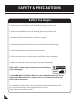
SAFETY & PRECAUTIONS Before You Begin... 1. Check your local building codes regarding footings, location, etc. 2. Select a site that allows enough working space around the shed. 3. Determine building foundation and anchor system. 4. Read and understand the Owner’s manual enclosed in the package. 5. Follow all directions and dimensions thoroughly. 6. Follow the steps given in the manual carefully for correct assembly. 7. Make sure all parts are present before you start assembling. 8.
SAFETY & PRECAUTIONS For your own safety, please read and follow these instructions during the shed assembly. 1. Always wear work gloves, long sleeves and eye protection during assembly of the shed. Some pieces of the shed contain sharp edges and can cause injury. 2. Be cautious with the tools used for the assembly of the shed.Familiarize yourself with the operation of all the power tools. 3. Children and pets should be kept away from the assembly site to avoid any distractions and accidents. 4.
IMPORTANT Wear eye protection when using any form of power tools. Do not use voltage power tools in a wet or damp enviornment to avoid electric shock. Do not use any part of the shed as a means of personal support while attaching componets during assembly. The shed must be constructed on a solid base foundation. A concrete pad or a large size concrete patio stone squares is recommended for suitable floor base. Make sure it is firm and level and will allow drainage away from the site.
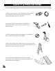
Parts List Note: Check all parts prior to installation. PARTS CODE QTY CODE QTY CODE B1LS B1RS B21Q B22Q B3S B4LS B4RS B5S CB1S CB2S CB3S CB2Q CB3Q CB4S CB6S DSHC MJ RS1S RS2FS RS2BS RS4S RS3LQ RS3SQ RS3LS RS3SS 1 1 1 1 1 1 1 1 1 1 1 2 1 1 1 1 2 2 1 1 2 1 1 1 1 RS9B RS5S RS6S RS14S CMB CMS CCS CCRS CCES CDLC 2 1 1 3 3 2 2 1 1 FDCLS 2 FDCRS 2 FCC 2 FMC 5 FRLC 2 CCF 3 CMF 2 LSH 2 RSH 2 RJ 2 PPG 43 PWS 43 PIN 43 ST 1.57meter.
Option -1 Right Side Door For Right side door follow the page no. 8-30 & 54-57.
Option -2 Left Side Door For Left side door follow the page no.
A. Foundation Note : Do not follow this Foundation instructions , if you have DURAMAX Foundation DuraMax must be installed on a level wooden platform or a level concrete foundation. Note Wooden Platform (Not Included) The following are a list of lumber and sizes you will need. Pressure Treated-Wood Studs: Exterior Grade (CDX): 3ea 2”x 4”x 89” (50 x 88.9 x 2260.6mm) 2ea 2”x 4”x 48” (50 x 88.9 x 1219.2mm) ) 50 ”( mm 2 L- BRACKET 3/4”(19mm) plywood 1ea 3/4”x 48”x 96” (19 x 1219.2 x 2438.
OPTION -1 RIGHT SIDE DOOR. B. Base channel. Note Parts Needed: 1. It is important that these instructions are followed step by step. 2. All parts are clearly marked and care should be taken to use correct one. 3. Don’t install under windy condition. 4. If iyou are building the shed against a wall, build it 2.5 ft. away then slide it in.
D. Walls & Columns Note All panels are clearly marked and care should be taken to use the correct one. Parts Needed: CODE QTY CODE QTY CB1S CB2Q CB3Q CB2S CB3S CB4S CB6S CCF CMF FCC FMC FDCLS FDCRS 1 2 1 1 1 1 1 3 2 2 3 2 1 CMB CMS CCS CCRS CCES CDLC CDRS FSPC SP SPS S1 S2 3 2 2 1 1 1 1 2 4 3 47 5 1 1 CDLC CDLC Fig.1 B1LS CDLC B1LS on Fr Le t 2&3 ft Fig.2 CDLC B1LS 10 Fig.
2 Note FSPC Check the stamped label on inside top of all panels. 2 FSPC CDLC FSPC CDLC FSPC CDLC Le 1 ft B1LS B1LS Fig.2 Fig.1 3 o Fr nt 1 FSPC CCS CCS B1RS CCS Fig.1 FSPC B1LS 2&3 S1 Fig.3 Fig.2 o Fr B1LS B1RS 4 Note Do not tighten the screw. Leave it loose.
5 CCF CCF 1&2 CB1S CB1S Fig.1 S1 Fig.2 CB1S 3 CB1S S1 CDLC o Fr Fig.3 nt 6 CB4S CDLC S1 S1 2 CDLC B1LS CB4S Fig.1 CB4S Fig.2 1 7 1 SP CMB SP CMB FSPC CCS Fig.1 B4LS S1 Fig.
8 CCF CCF CB2Q CB2Q S1 Fig.1 CMB 1&2 3 Fig.2 CMB CB2Q CB2Q S1 Fig.3 9 9 1 CMB CMB B22Q S1 Fig.1 Fig.2 3&4 CB2Q CB2Q CB2Q CMB SP CMB CMF CMB S1 2 CMF S2 Fig.4 Fig.3 10 1 SP SP CCS CCS CCS Fig.1 CCS S1 B22Q B3S 13 Fig.2 B3S Fig.
11 CMF 1&2 CMF CB3Q CB3Q CB3Q S1 Fig.2 Fig.1 12 CCS CCF CCF CB3Q 1,2&3 CB3Q CCS S1 Fig.1 CCS CB3Q Fig.2 CCF S2 Fig.3 13 1 FSPC FSPC CMB CMB B3S CCS Fig.1 S1 Fig.
14 CCF CCF 1&2 CB2S CB2S S1 Fig.1 3 Fig.2 CMB CB2S CB2S S1 Fig.3 15 FSPC SP SP CMB 16 1 CCES CCRS B21Q B3S CCRS CCES Fig.1 Fig.
CB2S 1&2 CCF CCF CB2S CB2S CCRS S1 Fig.1 Fig.2 18 CCRS 1 CCF S2 Fig.
20 CCF CCF 1&2 CB2Q 3 CB2Q S1 Fig.1 CB2Q Fig.2 CMS CB2Q S1 Fig.3 21 1 CMS CMS SPS CMS B4RS SPS S1 Fig.1 CB2Q CB2Q Fig.2 CB2Q 3&4 CMS CMF CMS S1 CMF S2 Fig.4 Fig.3 22 2 CMF CDRS CB3S B5S CDRS Fig.1 SPS S1 Fig.2 CMF 17 Fig.3 CB3S 4 CDRS CB3S S1 2&3 CB3S S1 Fig.
23 FMC 3&4 1&2 FMC 1&2 CMB CMB S1 Fig.1 Fig.2 1&2 FDCLS FDCLS CDLC CDLC S1 Fig.3 Fig.4 24 Ba ck 1&2 FCC FCC CCS CCS S1 Fig.1 FCC CCS Fig.3 18 Fig.2 3&4 FCC CCS Fig.
25 2 3&4 CCES 3&4 FDCRS FDCLS S1 S1 CDRS 1 CCES Fig.1 CMS Fig.2 CMS CDRS FMC FMC CMS Fig.3 19 CMS S1 Fig.
C.
1 Front roof structure assembly Make sure these holes up RS9B FRLC S1 RS1S RS1S S1 2 S1 RS9B 3 RS1S 21 RS2FS
4 Back roof structure assembly Make sure these holes up RS9B S1 RS1S FRLC S1 RS1S 5 S1 RS2BS RS9B 6 RS1S 22
7 RS3SQ S1 1 S1 RS3SQ RS3SS RS3LQ RS3SS RS3LQ RS3LS 2 RS3LS MJ MJ Fig.1 8 Fig.2 RJ RS3LQ RS3LQ RJ 3 RJ RS3SQ S1 Fig.1 RS3LQ Fig.2 RJ RJ 1&2 S1 RS3SQ Fig.
10 3 RS3LS RS3SS RS3LS FDCRS FDCRS CDRS 4 S1 Fig.1 RS3SS RS3LS S1 CCES CMS Fig.3 Fig.4 FDCLS FRLC 11 1&2 FMC FDCLS S1 RS3LS Fig.2 S1 S1 4 RS1S CDLC 3 CDRS Fig.1 Fig.2 FRLC CCES S1 2 RS1S FMC 1 S1 Fig.3 Fig.4 12 Do not fix screw here RS2FS RS2FS 3 RS1S RJ RJ Fig.1 RS2BS RS1S Fig.2 RS3SQ S1 RS3LQ RS3SQ 24 Fig.
13 S1 S2 RS3LQ RS2FS 3&4 RJ RS3LQ Fig.2 Fig.1 S2 RS2BS RS3SQ RJ S1 RS2BS RS3LQ RS3SQ RS3SQ Fig.3 1&2 Fig.4 14 S1 S1 FMC FMC RS3SQ 2 RS3SQ MJ RS3LQ 1 RS3LQ Fig.1 RS3LQ Fig.2 15 3 2 RS3SS RS3LS S1 S1 RS3SS RS2BS RS2FS Fig.1 25 Fig.
16 2 S1 RS5S RS6S RS2BS RS2FS RS9B RS9B S1 Fig.1 1 RS6S RS5S Fig.2 17 RS4S S1 S1 RS3LS 1 RS3SQ RS4S 3 RS4S RS3LQ Fig.1 Do not fix this hole RS5S Fig.2 2 4 RS4S RS4S RS4S S1 S7 RS3LQ Fig.3 Fig.4 18 S7 RS14S RS3LS S7 RS14S RS3LQ Fig.2 Fig.1 RS5S RS14S 3 RS14S 2 S7 22 26 1 RS14S Fig.
19 RS9B Front 1 RS1S DSHC DSHC S1 2 Fig.1 S1 DSHC Fig.2 20 2 CB6S CDLC RS1S CB6S S1 1 CB6S S1 Fig.1 Fig.
E. Roof panels Note Parts Needed: CODE QTY CODE QTY RPS FPLC FPRC DS RSH 3 1 1 1 2 PPG PWS PIN S3 43 43 43 8 ST 1.57 meter Apply silicone into the holes before inserting the pins. This is optional and should be done for heavy rain areas if needed. PPG PIN FPRC 2 1 FPLC PPG PIN PPG PIN FPRC Back Front Note Note Use a Screw driver to align the holes. Insert roof plugs & pins into roof panels only indicated. 3 Apply silicone around the roof plugs.
5 Note Roof Panel installation by using ladder from inside at missing Panels. 6 Back RPS PPG PIN RPS PPG PIN 7 RSH RSH 2 CDRS DS S3 S3 Fig.1 1 Fig.
Note Apply silicone around the perimeter of the base ‘U’ channel. Seal the corners, joints and base of door column. This is optional and should be done for heavy rain areas if needed. Base ‘U’ channel 1 Silicone Column Fig.1 Silicone Base ‘U’ channel Fig.2 Note For heavy rain areas, if a duramax foundation kit is not being used, you can fix a weather strip at the bottom of the door. This is optional and the part is not included.
OPTION -2 LEFT SIDE DOOR. B. Base channel. Note Parts Needed: 1. It is important that these instructions are followed step by step. 2. All parts are clearly marked and care should be taken to use correct one. 3. Don’t install under windy condition. 4. If iyou are building the shed against a wall, build it 2.5 ft. away then slide it in.
C. Walls & Columns Note All panels are clearly marked and care should be taken to use the correct one. Parts Needed: CODE QTY CODE QTY CB1S CB2Q CB3Q CB2S CB3S CB4S CB6S CCF CMF FCC FMC FDCLS FDCRS 1 2 1 1 1 1 1 3 2 2 3 1 2 CMB CMS CCS CCRS CCES CDLC CDRS FSPC SP SPS S1 S2 3 2 2 1 1 1 1 2 4 3 47 5 1 1 CDLC CDLC Fig.1 B1RS CDLC gh Ri B1RS Fro t 2&3 Fig.2 CDLC B1RS Ba 32 S1 Fig.
2 Note Check the stamped label on inside top of all panels. 2 FSPC CDLC FSPC FSP CDLC FSPC 1 FSPC CDLC Fro B1RS nt Fig.2 Fig.1 B1RS 33 CCS 1 FSPC B1LS B1RS CCS FSPC CCS CCS Fig.1 B1LS B1RS S1 Fig.2 Fro gh Ri nt 2&3 Fig.
5 CCF CCF CB1S CB1S 1 S1 Fig.1 Fig.2 2 CB1S CB1S S1 Fro CDLC Fig.3 6 CB4S S1 2 S1 B1RS CB4S Fig.1 CDLC Fig.2 CB4S 1 7 7 1 CMB SP FSPC CCS Fig.1 SP S1 B4RS CMB Fig.
88 CCF CCF S1 CMB CB2Q 1&2 CB2Q Fig.1 Fig.2 3 CMB CB2Q CB2Q S1 Fig.3 99 CMB 1 S1 CMB B21Q CMB Fig.1 SP Fig.2 3&4 CB2Q CB2Q CMB CB2Q CMF CMB Fig.3 S2 2 S1 CMF Fig.4 10 1 SP CCS CCS CCS Fig.1 S1 CCS B21Q B3S 35 Fig.2 B3S Fig.
11 1&2 CMF CMF CB3Q CB3Q CB3Q S1 Fig.2 Fig.1 12 CCS CB3Q CCS CCF 1,2&3 CB3Q Fig.1 CB3Q S1 CCF Fig.2 CCS CCF S2 Fig.3 13 FSPC FSPC 1 CCS SP Fig.1 CMB CMB 2 B3S 36 Fig.
14 CCF CCF 1&2 CB2S CB2S 3 S1 Fig.1 Fig.2 CMB CB2S CB2S S1 Fig.3 15 FSPC SP SP CMB 16 Note CCES Remove CCES from COAS. 17 Note COAS Remove COAS from CCRS .
18 19 CCES CCES CCRS COAS CCRS CCRS CCRS COAS 20 1 CCRS B22Q CCRS CCES B3S Fig.1 Fig.
21 CCRS CCRS CB2S CB2S CCF CB2S CCF 1&2 S1 Fig.1 Fig.
24 CCF CCF CCRS S1 CMS 1&2 CB2Q CB2Q 3 CCRS Fig.1 CB2Q Fig.2 CMS CB2Q S1 Fig.3 25 CMS 1 S1 SPS CMS B4LS SPS CMS Fig.1 Fig.2 3&4 CB2Q CB2Q CMS CMF CMS Fig.3 26 S1 CMF S2 2 Fig.4 CMF CDRS CB3S B5S Fig.1 CMS S1 SPS Fig.2 4 CDRS CMF CB3S CB3S CB3S S1 CMS 40 17 Fig.3 S1 Fig.
27 3&4 1&2 FMC 1&2 FMC CMB S1 CMB Fig.2 Fig.1 1&2 FDCRS S1 FDCRS CDLC CDLC Fig.3 Fig.4 Ba 28 ck 1&2 FCC FCC CCS CCS Fig.1 Fig.2 FCC FCC CCS CCS Fig.3 41 S1 Fig.
29 2 3&4 CCES FDCLS FDCRS S1 CDRS S1 1 CCES Fig.1 3&4 Fig.2 CMS CMS FMC FMC CDRS S1 CMS CMS Fig.3 30 42 Fig.
C.
1 Front roof structure assembly 1 2 Make sure these holes up RS9B FRLC RS1S S1 S1 3 RS1S S1 RS9B RS2BS 44
4 Back roof structure assembly 5 Make sure these holes up RS9B FRLC S1 RS1S RS1S 6 S1 S1 RS9B RS2FS 45
7 RS3SQ 1 S1 S1 RS3SS RS3SQ SS3SRS3SS R RS3LQ 2 RS3LS RS3LQ MJ MJ RS3LS JM Fig.2 Fig.1 8 RJ RS3LQ RJ RJ RS3LQ Fig.1 RS3SQ RJ Fig.2 S1 RS3LQ RJ 1&2 RS3SQ S1 Fig.
10 RS3LS 3 RS3SS RS3LS CCES FDCLS FDCLS CDRS 4 S1 Fig.1 Fig.2 FDCRS RS3LS 1&2 CMS FMC CMS RS3LS S1 RS3SS S1 CCES CMS Fig.3 11 1 CDRS Fig.4 FDCRS 4 FRLC S1 CCES S1 3 RS1S CDRS CDLC Fig.2 Fig.1 CCES 1 S1 FRLC CMB 2 CDRS RS1S S1 FMC CDLC CMB Fig.4 Fig.3 12 Do not fix screw here RS2FS RS2BS RS2BS 3 RS1S Fig.1 RS1S RJ RS3SQ RJ Fig.2 RS2BS RS3LQ RS2FS S1 1&2 RS3SQ 47 Fig.
13 S1 RS3LQ RS2BS RS2BS S2 1&2 RS3SQ RS3LQ RJ Fig.2 Fig.1 RS2FS RS2FS RS3LQ 1&2 S2 S1 RS3SQ RJ RS3SQ Fig.3 Fig.4 14 S1 S1 FMC FMC RS3SQ RS3SQ RS3LQ MJ Fig.1 2 RS3LQ RS3LQ 1 Fig.2 15 2 RS3SS RS3LS S1 S1 RS3LS RS2FS RS2BS RS2BS RS3SS Fig.1 48 1 Fig.
16 2 S1 RS6S RS5S RS2FS RS2BS 1 RS5S S1 RS6S RS9B RS9B Fig.2 Fig.1 17 RS4S RS3LS RS3SS S1 RS4S S1 RS3LQ Fig.2 Fig.1 1 RS3LS RS4S 3 4 Do not fix this hole RS4S 2 S1 RS4S RS3SQ RS6S RS4S RS3SQ RS3LQ S7 RS3LQ Fig.4 Fig.3 18 S7 RS3SS RS14S RS3LS S7 RS3LS RS14S RS3LQ Fig.1 Fig.2 RS14S RS6S RS14S 1 RS14S 3 RS3SQ RS14S 2 S7 RS3LQ 49 Fig.
19 1 Front RS9B RS1S DSHC DSHC 2 Fig.1 S1 Fig.2 S1 20 DSHC 2 CB6S CDLC RS1S S1 CB6S CB6S 1 S1 Fig.1 50 Fig.
E. Roof panels Note Parts Needed: CODE QTY CODE QTY RPS FPLC FPRC DS LSH 3 1 1 1 2 PPG PWS PIN S3 43 43 43 8 ST 1.57 meter Apply silicone into the holes before inserting the pins. This is optional and should be done for heavy rain areas if needed. PPG PIN FPRC 2 1 PPG PIN PPG PIN FPRC FPLC Back Front Note Use a Screw driver to align the holes. Insert roof plugs & roof pins into roof panels only indicated. 3 PIN PPG Ba Note Apply silicone around the roof plugs.
5 Roof Panel installation by using ladder from inside at missing Panels. 6 Note RPS RPS PPG PIN 7 LSH LSH 2 1 DS CDRS S3 Fig.1 Fig.
Apply silicone around the perimeter of the base ‘U’ channel. Seal the corners, joints and base of door column. This is optional and should be done for heavy rain areas if needed. Note Base ‘U’ channel 1 Silicone Column Fig.1 2 Silicone Fig.2 Note Base ‘U’ channel For heavy rain areas, if a duramax foundation kit is not being used, you can fix a weather strip at the bottom of the door. This is optional and the part is not included.
F. Ventilation Kit Parts Needed: CODE VC VCP Note TOOLS YOU WILL NEED QTY 2 4 VC Power Drill Dia 3/16” (5mm) drill bit Dia 1/2” (12.5mm) drill bit VCP Optional ventilation kits can be installed on any of the wall panels. However, we recomend mounting them on the top of the shed’s back wall. 3 2 1 ”) m 5m SP 6 3/1 .( VC SP Outside Outside SP 4 6 5 .5 12 mm ) /2” .
High wind area installation instructions Note: To ensure that your shed withstands high winds, you will need the following reinforcement. Parts needed (not included) : CODE DESCRIPTION S4 Dia. 4.2 x 16mm. (5/32” x 5/8”) Sheet Metal Screw M6 x 40mm. (1/4” x 1 1/2”) Anchor Bolt S5 QTY 30 24 1 Base ‘U’ Channel Using a carpenter square, line up corners.
3 Attach each Side Panel (SP ) on top to the Roof Structure (RS3LH , RS3H). Use a dia. 3mm (1/8”) drill with a power drill, make two equal distance holes on the Side Panel through the Roof Structure. Drive a self tapping screw (S4) through the Side Panel to the Roof Structure. Repeat this for every Side Panel. See blowup. RS3LH 3.0mm.
ADDITIONAL ACCESSORIES AVAILABLE These accessories are required in case of heavy snow or high wind areas. Please choose relevant accessories according to your needs. ANCHOR KIT (Soil) Wire rope with twist augers for sheds installed with foundation (Wood / Metal) on soil. For heavy wind area. ANCHOR KIT (Concrete) Eye bolt with wire rope for sheds installed with foundation (Wood / Metal) on concrete. For heavy wind area.
U.S. P olymers, Inc. 1057 S.