TM A Product of A L L P U R P O S E V I N Y L G A R D E N S H E D S Vinyl Garden Shed OWNER’S MANUAL / Instructions for Assembly ‘4 Ft SideMate’ Size 4 Ft x 8 Ft / 1.2 m x 2.4 m (Approx.) Patent #416.091 Ver: 4.0 Customer Service Hotline (800) 483-4674 www.uspolymersinc.com Your Total Solution To Maintenance Free Storage Sheds.
Duramax Garden Shed Limited Fifteen Year Warranty U.S. Polymer Inc. will send a replacement part free of charge, in the event of material defects and or workmanship for a period of fifteen years from the date of purchase. This warranty is extended only to the original purchaser. A purchase receipt or other proof of date of original purchase will be required before warranty service is rendered. In no event shall we pay the cost of flooring, labor, installation or any other costs related thereto.
SAFETY & PRECAUTIONS Before You Begin... 1. Check your local building codes regarding footings, location, etc. 2. Select a site that allows enough working space around the shed. 3. Determine building foundation and anchor system. 4. Read and understand the Owner’s manual enclosed in the package. 5. Follow all directions and dimensions thoroughly. 6. Follow the steps given in the manual carefully for correct assembly. 7. Make sure all parts are present before you start assembling. 8.
SAFETY & PRECAUTIONS For your own safety, please read and follow these instructions during the shed assembly. 1. Always wear work gloves, long sleeves and eye protection during assembly of the shed. Some pieces of the shed contain sharp edges and can cause injury. 2. Be cautious with the tools used for the assembly of the shed.Familiarize yourself with the operation of all the power tools. 3. Children and pets should be kept away from the assembly site to avoid any distractions and accidents. 4.
IMPORTANT Wear eye protection when using any form of power tools. Do not use voltage power tools in a wet or damp enviornment to avoid electric shock. Do not use any part of the shed as a means of personal support while attaching componets during assembly. The shed must be constructed on a solid base foundation. A concrete pad or a large size concrete patio stone squares is recommended for suitable floor base. Make sure it is firm and level and will allow drainage away from the site.
Parts List Note: Check all parts prior to installation. PARTS ACCESSORIES CODE QTY CODE QTY CODE B1LB B1RB B21 B22 B3C B4LC B4RC B5C CB1B CB2C CB3XB CB3B CB4B CB6C DSHC MJ RS1C RS2FC RS2BC RS3LH RS3H RS4C RS8B RS9B RS5A RS6H RS14B 1 1 1 1 1 1 1 1 1 1 2 2 1 1 1 3 2 1 1 1 1 2 2 2 2 2 6 CMB CMC CCB CCC CCCE CDLC CDRC FSP SP SPC RP FPLC FPRC RRSC DR 3 2 2 1 1 1 1 2 4 3 3 1 1 3 1 CBC 2 EPS 4 FDCLC 1 FDCRH 1 FCC 2 FMC 3 FCB 3 FMRC 4 FRLC 2 FRTC 1 FCB5C 1 LSH 2 RSH 2 RJ 2 PPG 52 PWS 52 PIN 52 STC 1.
Option -1 Right Side Door For Right side door follow the page no. 8-31 & 56-59.
Option -2 Left Side Door For Left side door follow the page no.
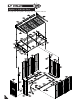
A. Foundation Note : Do not follow this Foundation instructions , if you have DURAMAX Foundation DuraMax must be installed on a level wooden platform or a level concrete foundation. Note Wooden Platform (Not Included) The following are a list of lumber and sizes you will need. Pressure Treated-Wood Studs: Exterior Grade (CDX): 3ea 2”x 4”x 89” (50 x 88.9 x 2260.6mm) 2ea 2”x 4”x 48” (50 x 88.9 x 1219.2mm) m) m (50 2” L- BRACKET 3/4”(19mm) plywood 1ea 3/4”x 48”x 96” (19 x 1219.2 x 2438.
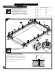
OPTION -1 RIGHT SIDE DOOR. B. Base channel. Note Parts Needed: 1. It is important that these instructions are followed step by step. 2. All parts are clearly marked and care should be taken to use correct one. 3. Don’t install under windy condition. 4. If iyou are building the shed against a wall, build it 2.5 ft. away then slide it in.
C.
1 Front roof structure assembly Make sure these holes up RS8B S1 Make sure these holes up RS9B FRLC RS1C RS1C S1 2 RS8B S1 RS9B 3 RS1C 11 RS2FC
4 Back roof structure assembly Make sure these holes up RS8B Make sure these holes up S1 RS9B FRLC RS1C S1 RS1C 5 RS8B S1 RS2BC RS9B 6 RS1C 12
7 S1 RS3H RS3H RS3LH RS3LH MJ 8 RJ RS3LH RS3LH RJ 3 RJ S1 Fig.1 Fig.2 RJ RJ 1&2 S1 RS3H Fig.3 9 Note Make Two sets.
Do not fix screw here 10 RS2FC RS2FC RS2BC RS1C RJ RJ Fig.1 RS1C 3 RS3H Fig.2 RS3LH RS2BC RS2FC S1 RS3H 1&2 Fig.3 11 RS5A 2 S1 RS2BC RS6H RS2FC RS5A RS6H RS6H RS8B Fig.1 S1 RS5A RS8B Fig.2 RS5A 1 4 3 S1 RS2BC RS2FC RS6H RS9B RS9B S1 Fig.3 Fig.4 12 S1 3 RS4C 3 2 RS3LH Fig.1 RS4C RS5A RS5A RS4C 2 RS4C RS4C 1 1 S7 14 Fig.2 S7 Fig.
D. Walls & Columns Note All panels are clearly marked and care should be taken to use the correct one. Parts Needed: CODE QTY CODE QTY CB1B CB2C CB3XB CB3B CB4B CB6C MJ FCB5C FMRC FCB FCC FMC FDCLC EPS CBC 1 1 2 2 1 1 2 1 4 3 2 3 1 4 2 FRTC DSHC CMB CMC CCB CCC CCCE CDLC CDRC FSP SP SPC S1 S2 S3 1 1 3 2 2 1 1 1 1 2 4 3 88 5 1 1 1 CDLC CDLC Fig.1 B1LB CDLC B1LB on Fr Le t ft 2&3 Fig.2 CDLC B1LB 15 Fig.
2 Note FSP Check the stamped label on inside top of all panels. 2 FSP FSP CDLC FSP CDLC Le 1 ft B1LB B1LB Fig.2 Fig.1 3 o Fr nt 1 FSP CCB CCB B1RB CCB Fig.1 B1LB 2&3 S1 Fig.3 Fig.2 B1RB o Fr B1LB 4 Note Do not tighten the screw. Leave it loose.
5 S1 1 FCB CB1B 2 CB1B CB1B CDLC Fig.2 Fig.1 S1 o Fr nt 6 S1 CB4B CDLC B1LB CB1B Fig.2 Fig.1 S1 CB4B 2&3 CB1B EPS CB4B CB4B 1 Fig.
8 1 SP SP CMB CMB FSP CCB B4LC S1 Fig.1 Fig.2 2 9 9 S1 FCB CB1B CB3XB 1&2 CB3XB CB3XB 3 S1 Fig.1 Fig.2 CMB CB3B CB3XB S1 Fig.3 10 CMB B22 S1 CMB SP MJ CB3XB 2&3 CB3XB CB3B CB3B CB3B CBC 1 S1 18 CMB Fig.1 Fig.2 Fig.
11 1 SP CCB SP CCB CCB Fig.1 S1 CCB B22 B3C B3C 2&3 Fig.2 12 Note Fig.3 Do not tighten the (S2) screw. Leave it loose. CB3B FCB S2 FCB CCB 1&2 Fig.1 S1 CCB CB3B FCB Fig.2 13 1 FSP FSP CMB CMB B3C CCB Fig.1 S1 Fig.
14 S1 FCB CB3B CB2C CB2C 1&2 3 Fig.1 Fig.2 S1 CB2C CMB CB2C S1 Fig.3 15 FSP SP SP CMB 16 1 CCC B21 B3C CCC CCCE Fig.1 Fig.
17 Do not tighten the(S2) screw. Leave it loose. Note CB2C FCB S2 CCC Fig.1 S1 CCC CB2C FCB CB2C FCB 1 Fig.2 18 S1 CB3B MJ CB3XB CB3B Fig.1 MJ CB3XB 1 2 S3 CB3XB FCB5C Fig.
20 S1 FCB CB2C CB3B CB3B 1&2 CB3B Fig.1 Fig.2 3&4 S1 CB3XB CMC CB3B CB3B MJ CB3XB CBC CB3XB S1 Fig.4 Fig.3 21 CMC CMC CMC SPC 2 CB3XB B4RC S1 S1 Fig.2 Fig.1 1 22 CDRC CDRC B5C CDRC S1 Fig.1 CB3XB S1 FCB5C SPC Fig.2 2&3 Fig.3 Note 22 EPS After completing the center band assembly,fully tighten the three center band fitting(FCB) to the corner columns (CCB) &(CCC).
23 FMC 1&2 1&2 FMC CMB CMB S1 Fig.1 Fig.2 1&2 24 Note Do not fix the screw now. FDCLC FDCLC CDLC Fig.1 23 CDLC Fig.
1&2 FCC FCC CCB CCB S1 Fig.1 FCC Fig.2 3&4 FCC CCB CCB Fig.3 Fig.4 S1 26 2 3 S1 CDRC FMRC Fig.1 CCCE 1 S1 FMRC Fig.2 CMC S1 FMRC 24 Fig.
27 FMRC RS2FC RS2FC 1&2 Fig.1 FMRC Fig.2 RS5A 28 S2 S1 RS3LH RS2FC 1&2 RJ 29 3 Fig.1 Fig.2 S2 S1 RS2BC RS2BC RJ RS3H RS1C Fig.2 Fig.1 S1 Fig.
30 RS3LH RS4C S1 FMC 31 S1 FRLC RS5A RS2FC 1&2 FMRC CDRC S1 Fig.1 S1 Fig.2 32 1&2 S1 FMRC FRLC CCCE RS2BC S1 RS6H Fig.1 22 26 S1 Fig.
33 S1 FMRC RS5A RS4C S1 34 DSHC RS1C Front RS8B 1 DSHC DSHC S1 S1 Fig.1 Fig.2 FRTC 2 35 CDLC CB6C 2 S1 CB6C Fig.1 1&3 EPS FSP CB6C S1 27 Fig.2 Fig.
E. Roof panels Parts Needed: CODE QTY CODE QTY RP FPLC FPRC RRSC RS14B DS 3 1 1 3 6 1 PPG PWS PIN RSH S3 STC 52 52 52 2 8 1.57 meter PPG PIN FPRC 2 1 PPG PIN FPLC PPG PIN FPRC Back Front Note Use a Screw driver to align the holes. Insert roof plugs & pins into roof panels only indicated. 3 Note Apply silicone around the roof plugs. This is optional and should be done for heavy rain areas if needed.
5 Note Roof Panel installation by using ladder from inside at missing Panels.
10 RSH RSH 2 1 CDRC DS DS S3 S3 Fig.1 Fig.
Note Apply silicone around the perimeter of the base ‘U’ channel. Seal the corners, joints and base of door column. This is optional and should be done for heavy rain areas if needed. Base ‘U’ channel 1 Silicone Column Fig.1 Silicone Base ‘U’ channel Fig.