
Floor/Ceiling Mount Installation Manual


DURASTAR.COM18
WARNING
All wiring must be performed strictly in accordance with the wiring diagram located
on the inside of the control box lid.
The signal cable enables communication between the indoor and outdoor units. You must first
choose the right cable size before preparing it for connection.
USE THE RIGHT CABLE
• Indoor Power Cable (if applicable): H05VV-F or H05V2V2-F
• Outdoor Power Cable: H07RN-F
• Signal Cable: H07RN-F
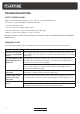
CABLE SIZING
Use a minimum of 16 AWG for power and signal cables connected to and between the indoor and
outdoor units.
Choose the correct size of cable
The size of the power supply cable, signal cable, fuse, and switch needed is determined by the
maximum current of the unit. The maximum current is indicated on the nameplate located on the
side panel of the unit. Refer to this nameplate to choose the right cable, fuse, or switch.
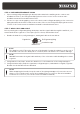
Wiring the Indoor Unit
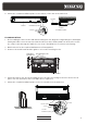
1. Prepare the cable for connection:
• Using wire strippers, strip the jacket from both ends of the cable to reveal about 6" of the
wires.
• Strip the insulation from the ends of the wires.
• Using a wire crimper, crimp u-lugs to the ends of the wires.
2. Open the front panel of the unit. Using a screwdriver, remove the cover of the electrical control
box.
3. Thread the signal cable through the wire outlet.
4. Unscrew the cable clamp below the terminal block and place it to the side.
5. Refer to the wiring diagram on the control box cover and connect the u-lugs to the terminal
block. Firmly screw the u-lug of each wire to its corresponding terminal.
6. After checking to make sure every connection is secure, use the cable clamp to fasten the
signal cable to the unit. Screw the cable clamp down tightly.
7. Replace the control box lid.
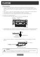
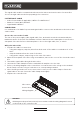
Wiring diagram
Control box
Wire outlet