Air-Cooled, All-Fuel Chimney for Fireplaces DuraChimney® ii Installation Instructions
A MAJOR CAUSE OF VENT RELATED FIRES IS FAILURE TO MAINTAIN REQUIRED CLEARANCES (AIR SPACES) TO COMBUSTIBLE MATERIALS. IT IS OF THE UTMOST IMPORTANCE THAT DURACHIMNEY II BE INSTALLED ONLY IN ACCORDANCE WITH THESE INSTRUCTIONS. NOTE: Read through all of these instructions before beginning your installation. Failure to install as described in this instruction will void the manufacturer’s warranty, and may have an effect on your homeowner’s insurance and UL listing status.
For the most up-to-date installation instructions, see www.duravent.com CONTENTS DuraChimney® ii AIR-COOLED, ALL-FUEL CHIMNEY FOR FIREPLACES Clearances | Permits | Applications | Installation Notes . . . . . . . . . . . . . . . 4 Equipment | Chimney Diameter | Chimney Height | Requirements . . . . . . . . . 5 Recommendations | Frame Opening Chart | Masonary Installation . . . . . . . 6 Chimney Sizing Chart . . . . . . . . . . . . . . . . . . . . . . . . . . . . . . . . . . . . . . . . . .
DuraChimney is designed to stay cool on the outside, to provide a hot draft on the inside, and to provide for a fire-safe design that protects both the chimney and the building. The double-wall air-cooled design allows the chimney to expand under high temperatures. Materials and Construction .016” 430 stainless steel inner wall and .021” galvanized steel outer wall. 2-inch clearance to combustibles. Listings UL Listed to UL 103 and ULC S604 standards.
EQUIPMENT & MATERIALS Drill / Driver Hammer Caulking Gun Plumb Bob Screwdrivers (Phillips & Standard) Tin Snips Saber or Keyhole Saw Level Dependable Ladder Tape Measure Proper Gloves and Shoes Eye Protection Non-hardening Waterproof Sealant 8-Penny Nails 600°F RTV Silicone Sealant Roofing Nails #8, 2-1/2” & 1-1/2” Wood Screws CHIMNEY DIAMETER Follow the fireplace manufacturer’s manual to determine required chimney diameter and clearances between combustible materials and your fireplace.
Table 1 Frame Opening Dimension Chart Diameter Framing Dimension 8" 16" X 16" 10" 17" X 17" 12" 19" X 19" 14" 21" X 21" 16" 23" X 23" ANCHOR PLATE OR ANCHOR PLATE WITH DAMPER MASONRY ANCHORS HI-TEMP SEALANT FIREPLACE RECOMMENDATIONS Always follow the fireplace manufacturer’s installation instructions. Installation: Install your fireplace as described by the fireplace manufacturer. Be sure to maintain all required clearances. Flues: Connect only one fireplace per chimney.
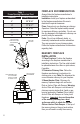
Table 2 Chimney Sizing Chart for Fireplace Installations Dotted line represents sample problem. Example shows fireplace opening as 36" wide and 30" high, and the chimney height as 20'. The correct flue size for the sample is 12" diameter pipe.
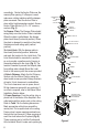
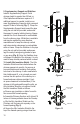
accordingly. Center the Anchor Plate over the masonry flue opening. If a Damper is used, make sure nothing interferes with the damper plate movement. Seal the Anchor Plate in place with a high-temperature sealant. Secure Anchor Plate with four (4) 2” x 1/4” masonry anchors (Fig. 2). 3a. Damper Plate: The Damper Plate should swing freely once the Anchor Plate is installed. When the chain is pulled down, the damper plate should close (horizontal position).
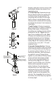
FRAMING Figure 5 Figure 6 INSTALL SUPP. SUPPORT IF HEIGHT EXCEEDS 50’ OR IF REQUIRED BY THE FIREPLACE MANUFACTURE EACH SUPPLEMENTARY SUPPORT UP TO 25 FEET OF CHIMNEY SECURE BRACKET TO FRAME MAINTAIN 2" CLEARANCE FROM CHIMNEY TO FRAMING Figure 7 dropping a plumb bob to the four corners of the opening below. Maintain the minimum 2-inch clearance/air-space. 6. Cut Roof Opening: If penetrating through the roof, determine and cut an opening in the roof directly above the opening below.
9. Supplementary Support and Stabilizer: Install a Supplementary Support if total chimney height is greater than 50-feet, or if the fireplace manufacturer requires it. If additional support is needed, install one or more Supplementary Supports which can each support 25-feet of chimney (Fig. 7). Clamp the Supplementary Support band around the pipe using the nut and bolt provided, and anchor the support to nearby building framing. Always maintain the 2-inch clearance to combustibles from the chimney pipe.
(4) ROOF RADIATION SHIELDS CHASE ENCLOSURE Figure 11 1/2 INCH MINIMUM AIR SPACE ESTABLISHED BY SPACERS 1/2 INCH AIR SPACE CHASE TOP FLASHING REQUIRED SPACERS 1/2 " Figure 12 1 1/2” VENTILATION OPENING AROUND CHIMNEY PIPE Figure 13 (2) 8-penny nails or two (2) #8, 1-1/2” wood screws per side (Fig. 10). e. Wrap the Collar of the Attic Insulation Shield around the chimney and fasten it loosely. Slide the Collar down to meet the Attic Insulation Shield.
SEALANT CHASE TOP COLLAR SCREW OR POP-RIVET Figure 14 SEALANT 6" MIN. 3' MINIMUM ABOVE ROOF OPENING STORM COLLAR Figure 15 TERMINATION CAP Figure 16 12 Ensure the minimum ½-inch spacing and perimeter ventilation requirements are met as show in Figure 12. Secure the Chase Top Collar Section to the field-fabricated chase top with sheet metal screws or rivets (Fig. 14). Seal Chase Top Collar Section to chase top with non-hardening waterproof sealant to ensure a weather tight connection.
14. Enclosures: Enclose chimneys where they pass through occupied spaces, including closets. Always maintain at least a 2-inch clearance between the chimney and any combustible materials. Interior enclosures may be constructed with standard framing and sheathed with sheetrock or plywood. Use a Wall Strap or Stabilizer at least every 8 feet to maintain a minimum of 2-inch of air space between the chimney and combustible materials. until the clamp is firm.
Table 3 DuraChimney II Elbow Offset Chart Size 8" I.D. Size 10" I.D. Size 12" I.D Size 14" I.D. Size 16" I.D.
CHIMNEY MAINTENANCE 1. Creosote and Soot: When wood is burned slowly, it produces tar and other organic vapors which combine with expelled moisture to produce creosote. The creosote vapors condense in the relatively cool chimney flue of a slow-burning fire. As a result, creosote residue accumulates on the flue lining. When ignited, this creosote makes an extremely hot fire. 2. Access: Chimneys must be installed so that access is provided for inspection and cleaning. 3.
DURAVENT WARRANTY DuraVent, Inc. provides this limited lifetime warranty for all of its products to the original purchaser, with the exception of Ventinox (lifetime), DuraBlack (five years) and all Termination Caps (five years). Subject to the limitations set forth below, DuraVent warrants that its products will be free from substantial defects in material or manufacturing, if properly installed, maintained and used.