
Installation Guide


11
pipe is to be installed on the exhaust
outlet.
3. Once securely installed to exterior, verify
exhaust pipe cannot be removed from
termination cap.
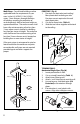
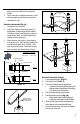
Stainless Horizontal (Fig.16)
1. Cut opening in the wall.
2. Add Trim Plates and locking band (if
applicable) to nal pipe length before
installing. Make sure anges are facing
towards the wall. Use non-hardening
sealant where necessary.
3. After exterior trim plate is mounted to
wall, measure 3" from exterior plate and
cut o female pipe end. Duburr. Seal
pipe to exterior plate. Slide Bird screen
over cut pipe end and tighten clamp.
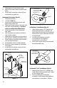
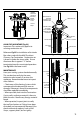
Figure 19
EXHAUST
AIR INLET
Figure 18
TERMINATION
CAP
FLASHING
STORM COLLAR
SUPPORT CLAMP
Figure 17
CENTERLINE OF
EXHAUST OUTLET
OF APPLIANCE
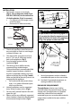
Vertical Concentric (Fig.18)
1. Locate penetration. (Fig.17)
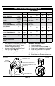
2. Cut hole in roof. (Table 3)
3. Cut hole in ceiling above appliance.
• Cut hole(s) big enough for pipe in all
ceilings above appliance if installing
in a multi story installation.
4. Firestop each ceiling penetration.
5. Attach ashing to roof. (Fig.18)
• Slide storm collar onto ashing if
using the Adjustable Roof Flashing.
6. Slide vertical termination into ashing
from above until seated on ashing.
7. Plumb Termination and mount support
bracket to structure.
CUT LINE
THROUGH HOLE SIZING
4PPS: 4.125" 5PPS: 5.25"
6PPS: 6.125" 8PPS: 8.00"
EXTERIOR PLATE
INTERIOR PLATE
PP PIPE
INITIAL
FINAL
BIRD
SCREEN
CLAMP
FLANGES
Figure 16