
Submittal

16
INSTALLATION
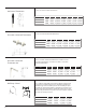
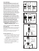
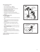
1. Pipe lengths may be cut to length (Fig.5). If the
Locking Tab is removed use the new Locking Clamp
(Fig.2a PPS-LC) or alternative clamp ( Fig.3 PPS-PAC
/ PPS-LBC) for the connection.
• Cut square (not at an angle) to the end of the
pipe.
• Remove burrs before assembly.
2. Check with appliance manufacturer for any
restrictions or limits on vent length, number of
elbows, etc.
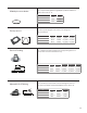
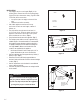
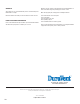
3. The slope of the vent pipe must be at least 1.8°
(3/8” rise per ft run, 31mm per meter) back to the
appliance. Ensure there are no dips in the system
where condensate can collect. (Fig. 6)
4. Every horizontal section must be supported. (Fig. 7)
5. The venting system shall be securely supported using
suitable hangers. Duravent hardware is recommended;
field supplied support hardware suitable to the AHJ is
acceptable, hardware must not deform or damage the
vent. (Fig. 6 and 7) Make sure the load of the vent
system is not supported by the appliance.
• On Duravent and other certain clamp styles, 3/8” or
greater All-thread may be used as an extension.
6. Vertical installations must be supported every 10 feet (3
meters) or less. (Fig.7)
7. Elbows and Tees are sufficiently supported when a
bracket is fixed at the female end of the connected straight
section. (Fig. 7)
8. Vertical components can be insulated in unconditioned
space or when ran outside.
9. Use black UV protected components on venting installed
on the exterior.
Figure 5
MARK
CUT WITH
HACKSAW
DEBURR
Figure 6
PP Pipe sections must be disengaged 1/4”-
5/8” per joint (to allow for expansion) and
sloped 1.8°(3/8”per ft) back to the appliance
per Fig.6 for proper condensate flow.
IMPORTANT
Figure 7
12"
3/8"
MIN
1/4" 5/8"
7.5mm 15mm
TO APPLIANCE
MAX
5FT
1.5m
ATTACH WALLSTRAP 1" TO 12"
FROM LOCKING BAND
3/8" ALL
THREAD
LOCKING CLAMPS
OR BANDS ARE
REQUIRED AT EVERY
EXHAUST JOINT
WALLSTRAP
MINIMUM 1PER
HORIZONTAL PIPE
SECTION
MAX
10FT
3M