
PolyPro Installation Supplement

DuraVent - PolyPro Instruction Updates
New Locking Clamp & Support Requirements
PolyPro
®
L273-SUP_820016826_Install Instructions_PolyPro_07-11-19
DuraVent is proud to announce a new and
improved Locking Clamp to secure the joint of
PolyPro Single-Wall venting. To install, follow
the steps below:
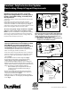
1. Verify the gasket is seated evenly inside the groove in the
female end.
2. Assemble the joint by passing the male end of the
Polypro Pipe through the Locking Clamp on the hose clamp
side and into the female end of the PolyPro pipe, (Fig.1).
3. Hook the Locking Clamp onto the gasket extrusion on the
female end and tighten down on the hose clamp.
The new Locking Clamp design is backwards compatible
with pipe sections designed for use with the Locking
Band. Use pliers to break o the Locking Tab with a twisting
motion. Once removed, install the pipe section following
the Locking Clamp instructions above. Locking Clamps can
be purchased separately in packs of 12.
NEW
LOCKING
CLAMP
TIGHTEN HOSE
CLAMP TO SECURE
JOINT
VERIFY LOCKING
CLAMP HOOKS
UNDER GASKET
EXTRUSION
Fig.1. Screws are not allowed for joint connection.
Never penetrate the wall of PolyPro Single-Wall vent
pipe. (Exception: a stainless steel screw may be used
outside the building on exterior terminations and
exterior joints to orient an elbow, etc).
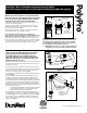
• IMPORTANT: Locking Bands or Locking Clamps are
mandatory on all exhaust vent joints.
MAX
5FT
1.5M
ATTACH WALLSTRAP 1" TO 12"
FROM LOCKING BAND
3/8" ALL
THREAD
LOCKING CLAMPS
OR BANDS ARE
REQUIRED AT EVERY
EXHAUST JOINT
WALLSTRAP
MINIMUM 1PER
HORIZONTAL PIPE
SECTION
MAX
10FT
3M
Figure 3
DuraVent is also introducing new vent
support requirements for the PolyPro product
line. With the new support requirements,
horizontal venting is now allowed to be run at
a minimum 3/8” rise per foot of run pitch.
Check with appliance manufacturer for any restrictions or
limits on vent length, number of elbows, etc.
1. The slope of the vent pipe must be at least 1.8° (3/8” rise
per ft run, 31mm per meter) back to the appliance. Ensure
there are no dips in the system where condensate can
collect. (Fig.2)
2.
Every horizontal vent run must be supported. (Fig.3)
3. The venting system shall be securely supported using
suitable supports. Supports made by DuraVent are
recommended; eld supplied supports, such as all-thread or
plumbers tape, that are approved by the AHJ is acceptable. All
supports must not deform or damage the vent. Ensure the load
of the vent system is not supported by the appliance.
• Duravent Wallstraps are designed for use with 3/8”-
16 all-thread rod to extend from a wall, ceiling, or
anchoring point.
4. Vertical pipe lengths must be supported every 10 feet (3
meters) or less. Horizontal pipe lengths must be supported
every 5 feet (1.5 meters) or less. (Fig.3)
5. Elbows and Tees are suciently supported by attaching a
wall support within 1” to 12” of the pipe joint holding the Elbow
or Tee. (Fig.3)
Figure 2
12"
3/8"
MIN
1/4" 5/8"
7.5MM 15MM
TO APPLIANCE