PolyPro Single-Wall Gas Vent System for Category II & IV Gas-Burning Appliances ® PolyPro Installation Instructions
A MAJOR CAUSE OF VENT RELATED FIRES IS FAILURE TO MAINTAIN REQUIRED CLEARANCES (AIR SPACES) TO COMBUSTIBLE MATERIALS. IT IS OF THE UTMOST IMPORTANCE THAT POLYPRO® BE INSTALLED ONLY IN ACCORDANCE WITH THESE INSTRUCTIONS. Warning CARBON MONOXIDE POISONING HAZARD. Failure to follow the steps outlined below for each appliance connected to the venting system being placed into operation could result in carbon monoxide poisoning or death.
For the most up-to-date installation instructions, see www.duravent.com CONTENTS PolyPro PolyPro Single-Wall Gas Vent System listing. . . . . . . . . . . . . . . . . . . . . . . . . . . . . . . . . . . . . . . . . . . .. . . . . . . . . . . . . . . . . 4 Application. . . . . . . . . . . . . . . . . . . . . . . . . . . . . . . . . . . . . . . . . . . .. . . . . . . . . . . 4 Permits . . . .. . . . .. . . . . . . . . . . . . . . . . . . . . . . . . . . . . . . . . . .. . . . . . . . . . . . . . . . .
Listing Listed to ULC S636 Rated Class IIA, IIB, and IIC vent system maximum temperature 230°F (110 °C) maximum positive pressure 15 in-w.c. Massachusetts Plumbers Board, # G1-0811-42. APPLICATION ANSI Category II and IV gas-burning appliances. Appliances specifically tested and listed to use M&G DuraVent PolyPro Venting PERMITS Check with your local Building Official, Fire Official, or other authority having jurisdiction regarding permits, restrictions, and installation inspections in your area.
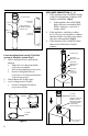
important Warning CARBON MONOXIDE POISONING HAZARD Failure to follow these installation instructions could result in personal injury or death The vent system must be compliant in accordance with local code requirements and appropriate National Codes: In the US: NFPA 54 / ANSI Z223.1 National Fuel Gas Code or the International Fuel Gas Code. In Canada: CAN/CGA-B149.1 Natural Gas Installation Code or CAN/CGA149.2 Propane Installation Code. JOINT CONNECTIONS PolyPro to PolyPro (Fig.
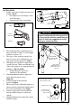
locking band Male End feMale End Push down to lock VERIFY GASKET IS SEATED IN FEMALE END OF PIPE pry out to unlock Appliance Connection: 2" - 4" 1. If the appliance has a PVC/CPVC female outlet use the Appliance Adapter/ PVC Adapter and Clamp. (Fig.4) • If the appliance has a PVC/CPVC Male outlet use a matching PVC/ CPVC coupling to convert to a female outlet. 2.
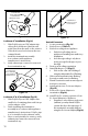
Installation 1. PolyPro vent pipe lengths may be cut to length. (Fig.6) • Cut square (not at an angle) to the end of the pipe. • Remove burrs before assembly. to appliance 5/8" min 1/4" - 5/8" (7.5mm - 15mm) Mark 12" Figure 7 important cut with hacksaw PP Pipe sections must be disengaged 1/4"5/8" per joint (to allow for expansion) and sloped 3° back to the appliance per Fig.7 for proper condensate flow. Deburr all-thread Figure 6 2. 3. 4. 5. 6. 7. 8. 9.
Terminations: Horizontal Single Pipe (Fig.10) 1. Locate penetration in wall 2. Cut or cut and frame hole (Table 3) 3. Attach Inner Plate to wall 4. Attach / seal Outer Plate to outside wall 5. Line up keyway, slide black pipe (UV Protected) or termination through plates 6. If termination is used attach with screws • Align tabs with mounts 7. Add additional components to raise vent level if desired (vent to be 12" above grade or ave snow level) 8. Remove gasket and install Bird Guard into end of pipe. (Fig.
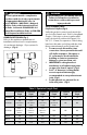
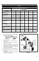
Table 3 Wall & Ceiling Penetration Sizing Table Vent Diameter Termination 2" 3" 4" 5" 6" 8" 4 1⁄8" 105mm 5 1⁄8" 130mm 6 1⁄8" 155mm N/A N/A N/A TWIN PIPE HORIZONTAL CLASS IIB 7 3⁄8" x 25⁄8" 187mm x 65mm 8 3⁄8" x 37⁄8" 212 x 85mm 9" x 43⁄8" 228 x 100mm N/A N/A N/A TWIN PIPE HORIZONTAL CLASS IIC (Framing Dimensions) 8" x 3" 200 x 77mm 8 7⁄8" x 37⁄8" 225 x 98mm 9 3⁄8" x 4 3⁄8" 238 x 112mm N/A N/A N/A SINGLE HORIZONTAL CLASS IIB 25⁄8" 65mm / 3 3⁄8" " 85mm 4" " 100mm N/A N/A N/A
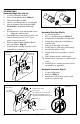
Polypro pipe w/pvc adapter (supplied with termination kit) bracket centerline of exhaust outlet of appliance Figure 14 Figure 16 Lochinvar 2" installation (Fig.14) 1. Slide PolyPro pipe w/ PVC adapter into oblong hole and down. Brackets will point away from the wall, on the exterior of the house, and rest between the two outward beads. 2. Install the termination assembly in accordance with appliance manufacturer’s instructions. 3. Verify exhaust pipe cannot be removed from termination cap.
Termination cap 6. storm collar 7. flashing where exposed to sunlight. Maintain 12 in. (305mm)min. clearance above highest anticipated snow level Maximum of 24 in.(614mm) above roof Install Poly Pro venting system to/from black pipe to appliance bird guard support clamp UV protected pipe Figure 17 rubber flashing Figure 19 exhaust air inlet Figure 18 Vertical single pipe (Fig.19) 1. Locate penetration (Fig.16) 2. Cut hole in roof (Table 3) 3.
Polypro WARRANTY M&G DuraVent, Inc. (“DuraVent”) provides this warranty for PolyPro® for ten years. Subject to the limitations set forth below, DuraVent warrants that its products will be free from defects in material or manufacturing, if properly installed, maintained and used. DuraVent products are fully warranted if installed only by a professional installer. This Warranty is transferable from the original homeowner to the buyer of the home within the warranted ten years.