Multi-fuel venting system. UL 641, ULC S609, and ULC/ORD C441.
A MAJOR CAUSE OF VENT RELATED FIRES IS FAILURE TO MAINTAIN REQUIRED CLEARANCES (AIR SPACES) TO COMBUSTIBLE MATERIALS. IT IS OF THE UTMOST IMPORTANCE THAT PELLETVENT BE INSTALLED ONLY IN ACCORDANCE WITH THESE INSTRUCTIONS. NOTE: Read through all of these instructions before beginning your installation. Failure to install as described in this instruction will void the manufacturer’s warranty, and may have an effect on your homeowner’s insurance and UL listing status.
For the most up-to-date installation instructions, see www.duravent.com CONTENTS PelletVEnt Venting Systems for Pellet, Corn, Oil and Multi-fuel Stoves Clearances And Applications, Important: Corn-Burning & mulit-fuel Appliances, Vent Listing . . . . . . . . . . . . . . . . . . . . . . . . . . . . 4 Tools And Equipment You May Need, PERMITS, General Installation Instructions . . . . . . . . . . . . . . . . . . . . . . . . . . . . . . . . . . . . . . . . . 5 INSTALLATION INTO A MASONRY FIREPLACE . . . .
CLEARANCES AND APPLICATIONS DuraVent’s PelletVent and PelletVent for multifuels is listed by Underwriters Laboratories as vent for listed oil-, pellet-, and corn-burning (multi-fuel) appliances. PelletVent is also listed as a masonry reliner, in which case the minimum clearance is 0” from vent to masonry, and 0” clearance from the masonry to nearby combustibles. Never fill any required clearance space with insulation or any other materials.
improvised solutions. 4. Practice good workmanship. Sloppy work could jeopardize your PelletVent installation. 5. Never use a vent with an inside diameter that is smaller than the appliance flue outlet. 6. Multistory: Where PelletVent passes through the ceiling, use DuraVent Firestop/Support assembly. 7. PelletVent placement: When deciding the location of your stove and vent, try to minimize the alteration and reframing of structural components of the building. 8.
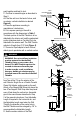
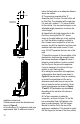
1 INCH MINIMUM VERTICAL CAP STORM COLLAR FLASHING ATTIC INSULATION SHIELD CEILING SUPPORT FIRESTOP SPACER ATTIC INSULATION PELLET VENT PIPE PIPE ADAPTER SEE TABLE 1 FOR FRAMING REQUIREMENTS STOVE Figure 1 and ceilings, always install a Ceiling Support Firestop Spacer. F. When the PelletVent enters the Attic, install an Attic Insulation Shield around the vent (Figures1 & 3). This will prevent insulation and debris from collecting near the vent pipe.
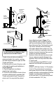
push together and twist to lock. C. Continue to assemble pipe as described in Step 2. 4. If the flue exit is on the back of stove, and an exterior vertical installation is desired Figure 4): A. Place the appliance according to manufacturer’s instructions. B. Cut a square opening in the wall in accordance with the dimensions in Table 1. The black portion of the Wall Thimble is to be attached to the interior wall, and the galvanized portion (stainless steel on CornVent) is to be attached to the exterior wall.
TEE SUPPORT BRACKET / WALL STRAP 6 INCHES MINIMUM DOUBLE TEE WITH CLEAN-OUT ADAPTER 4 FT. ROUND HORIZONTAL CAP (OPTIONAL) OPTIONAL HOUSE SHIELD Figure 4 SQUARE HORIZONTAL CAP GALVANIZED EXTERIOR (STAINLESS STEEL FOR CORNVENT) 6 INCH MINIMUM Figure 6 BLACK INTERIOR Figure 5 Warning Do not install any insulation or other material inside the Wall Thimble. Thimble to the wall with non-hardening waterproof sealant. As an option, you may also seal the gap between the pipe and Wall Thimble with sealant.
(b) Not less than 4 ft. (1.2m) below, 4 ft. (1.2m) horizontally from or 1 ft. (305mm) above any door, window or gravity air inlet into any building. (c) Not less than 2 ft. (0.61m) from an adjacent building and not less than 7 ft. (2.1m) above grade when located adjacent to public walkways. 6. If it is desired to attach to an existing 6”, 7” or 8” DuraTech, DuraPlus or DuraChimney chimney, either roof supported, or ceiling supported: (Figure 7). A.
C B TOP VIEW 12 INCHES TO END OF PIPE A Figure 8 Figure 9 installation instructions. 3. Measure and record the dimensions as shown in Figure 8. 4. Use dimension “A” to determine total pipe requirements. Add 12 additional inches to 10 insure the termination is an adequate distance above the roofline. 5. The gross pipe required will be “A” dimension plus 12 inches. Five feet of this will be Flex Pipe. The remainder will be rigid pipe. For each joint, subtract 1-1/ 2 inches to allow for the overlap.
PELLET VENT CAP TALL CONE FLASHING RIGID PELLET VENT PELLET VENT CAP SCREW STORM COLLAR TO OUTER LINER OF PIPE WITH NONHARDENING SEALANT SHEET METAL SCREWS. THIS WILL SUPPORT SYSTEM.
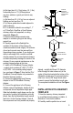
NON-HARDENING SEALANT TRIM BASE TO FIT FLUE TILE USE MASONRY ANCHORS TO SECURE FLASHING TO MASONRY Figure 15 REDUCTION COLLAR OR TRIM COLLAR TEE TEE Figure 16 FILL SPACE BETWEEN PIPE AND MASONRY WITH GROUT Figure 17 Cone Flashing modified to fit a chimney where the tile liner protrudes above the masonry, as another alternate termination technique. This completes the masonry installation. 12 INSTALLATION THROUGH SIDE OF MASONRY CHIMNEY 1.
push it into the Tee, while twisting to lock it. 7. Once the horizontal pipe section is in place, the space between the pipe and the masonry may be filled with high temperature grout, as shown in Figure 17, if desired. 8. Install the Reduction Collar or Trim Collar, the 90° Elbow, and the vertical pipe section going to the appliance. An Adjustable Pipe length will probably be needed, as well as a Pipe Adapter. 9.
12” MINIMUM CATHEDRAL CEILING SUPPORT BOX LEVEL TRIM 2” BELOW FINISHED CEILING Figure 22 TRIM CLAMP Figure 23 USE NONHARDENING SEALANT WHERE STORM COLLAR SITS ON FLASHING Figure 24 larger than the dimensions of the Support Box. (Figure 19). The rectangular hole should be centered on the small hole which you drilled through the ceiling to mark the 14 location. Again, verify that you are not cutting through rafters or framing members. 6.
CLEANING AND MAINTENANCE 1. Have your system cleaned by a certified chimney sweep if you have doubts about your ability to clean it. Use a plastic or flexible steel brush. Do not use a stiff brush that will scratch the stainless steel liner of your system. 2. PelletVent systems must be installed so that access is provided for inspection and cleaning. 3. The pellet vent should be inspected at least once every month during the heating season. 4. Do not use chemical cleaners. They can damage the vent pipe. 5.
M&G DURAVENT WARRANTY M&G DuraVent, Inc. (“DuraVent”) provides this limited lifetime warranty for all of its products to the original purchaser, with the exception of Ventinox® (lifetime), PolyPro® (ten years), DuraBlack® (five years) and all Termination Caps (five years). Subject to the limitations set forth below, DuraVent warrants that its products will be free from substantial defects in material or manufacturing, if properly installed, maintained and used.