
PolyPro Installation Manual


12
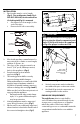
8. Install gaskets into Co-Linear Adapter (if
applicable). (Fig.12)
9. Connect Co-Linear Adapter to
termination (if applicable). (Fig.18)
10. Install Poly Pro venting system to/from
Co-Linear Adapter or termination to
appliance.
BLACK
UV PROTECTED PIPE
RUBBER FLASHING
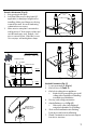
Figure 19- Vertical Pipe Termination
RIGID BLACK
UV PROTECTED
POLYPRO
GASKET
PLATE
STAINLESS
RELINE
HANGER
BRACKET
RIGID
POLYPRO
STAINLESS
UPPER
SUPPORT
PLATE
GASKET PLATE
/ HANGER
MOUNT
HARDWARE
FLANGE
BIRD GUARD
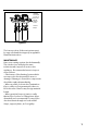
Figure 20
CLEARANCE
HOLE
1.75" MAT'L
SPACE MIN
Upper supports may be eld supplied and
listed, the listing requires: Min thickness of 24
ga (0.020") SS, no larger than 18" Dia or 18"
max length rectangle, 4 vent runs max per
support. The listing requires clearance holes
no larger than 5 1/8" Dia, with spacing 1 3/4"
apart.
The upper support plate (with a ange for
B vent and factory built chimney, Fig.21)
must be axed to the top of the conduit via
screws. Anchor bolts must be used when
attaching a at support plate to the top of
Masonry or other chase (not shown). Support
plate must be weather tight. The SS Hanger
Bracket is installed under the Gasket Plate
and axed to the top of the support plate
with screws (Fig.21). Use non-hardening
sealant as required.
Vertical single pipe (Fig.19)
1. Follow instructions for Vertical
Concentric Termination.
2. Attach ashing to roof. (Fig.19)
• Rubber boot ashing or similar,
ensure an eective, leak-proof seal
is maintained.
• Use BLACK UV protected pipe.
3. Maintain 12 in. (305mm) min. clearance
above highest anticipated snow level,
max 24 in. (610mm) above roof.
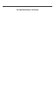
MULTIPLE VENTS IN ONE CONDUIT
Fig.20
Multiple PolyPro vent systems may be
installed within one conduit. Listed 2"-4"
M&G components must be used, and the
conduit (if pre-existing) must be inspected
and deemed sound.