Pellet-fuel venting system.
A MAJOR CAUSE OF VENT RELATED FIRES IS FAILURE TO MAINTAIN REQUIRED CLEARANCES (AIR SPACES) TO COMBUSTIBLE MATERIALS. IT IS OF THE UTMOST IMPORTANCE THAT PELLETVENT BE INSTALLED ONLY IN ACCORDANCE WITH THESE INSTRUCTIONS. NOTE: Read through all of these instructions before beginning your installation. Failure to install as described in this instruction will void the manufacturer’s warranty, and may have an effect on your homeowner’s insurance and UL listing status.
For the most up-to-date installation instructions, see www.duravent.com CONTENTS PelletVent® VENTING SYSTEMS FOR PELLET FUEL CLEARANCES AND APPLICATIONS . . . . . . .. . . . . . . . . . . . . . . . .. . . . . . . . .. . . . . . 4 VENT LISTING, INSTALLATION NOTES . . . . . .. . . . . . . . .. . . . . . . . .. . . . . . . . . . . . 4 TOOLS AND EQUIPMENT YOU MAY NEED, PERMITS . . . . . . . . . . . . . . . . . . . . . 5 GENERAL INSTALLATION INSTRUCTIONS . . . . . . . . . . . . . . . . . . . . . . . . . . .
CLEARANCES AND APPLICATIONS DuraVent’s PelletVent is listed by Underwriters Laboratories as a vent for listed oil-, pellet-, (multi-fuel) appliances. PelletVent is also listed as a masonry reliner, in which case the minimum clearance is 0” from vent to masonry, and 0” clearance from the masonry to nearby combustibles. Never fill any required clearance space with insulation or any other materials (except insulation explicitly approved by DuraVent as noted below).
not eliminate the need for inspection and cleaning. During the heating season, inspect monthly, and clean at least once a year. PERMITS Contact your local building department or fire officials regarding any needed permits, restrictions, and installation inspection requirements in your area. GENERAL INSTALLATION INSTRUCTIONS PelletVent is listed with a minimum 1” clearance to combustibles. Refer to Table 1 for framing requirements needed for these components. 1.
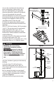
VERTICAL CAP 1 INCH MINIMUM STORM COLLAR FLASHING ATTIC INSULATION SHIELD CEILING SUPPORT FIRESTOP SPACER ATTIC INSULATION PELLET VENT PIPE PIPE ADAPTER SEE TABLE 1 FOR FRAMING REQUIREMENTS STOVE Figure 1 to be attached to the interior wall, and the galvanized portion is to be attached to the exterior wall. The Wall Thimble adjusts to fit walls from 3”-8” thick (Figure 5). C.
Cap can be swiveled to be directed away from nearby objects (fence, plants, etc.), but must still be pointing in a generally downward direction. Important: Horizontal Caps must be pointed in a generally downward direction to insure rain and snow do not enter the cap, and cause potential damage to the appliance. Either vent Cap should be at least 6” from the wall. C. Follow the appropriate code for proper distance of exit terminal from windows and openingsNFPA 211 (2010 ed.) Section 10.4 Termination: 10.4.
TEE SUPPORT BRACKET / WALL STRAP 6 INCHES MINIMUM DOUBLE TEE WITH CLEAN-OUT ADAPTER 4 FT. OPTIONAL HOUSE SHIELD Figure 4 HORIZONTAL CAP GALVANIZED EXTERIOR 6 INCH MINIMUM Figure 6 BLACK INTERIOR Figure 5 adapter or connector going into the Ceiling Support Box. B. Visually inspect with a flashlight the condition of the interior of the chimney for cleanliness and structural integrity. All evidence of soot and creosote must be removed from the existing chimney system.
determine it’s structural condition. 2. Carefully read the pellet stove or insert installation instructions. 3. Measure and record the dimensions as shown in Figure 8. 4. Use dimension “A” to determine total pipe requirements. Add 12 additional inches to insure the termination is an adequate distance above the roofline. 5. The gross pipe required will be “A” dimension plus 12". Five feet of this will be Flex Pipe. The remainder will be rigid pipe. For each joint, subtract 1-1/ 2" to allow for the overlap.
C B TOP VIEW 12 INCHES TO END OF PIPE A through the flashing to the desired height. Mark where the Storm Collar will go. Slip the Storm Collar down over the pipe, and affix it to the pipe with a 1/4”long stainless steel sheet metal screw. (Figures 13 & 14). The Storm Collar will then support the entire vent system. Install the Cap. Seal the joint at the Storm Collar, and any other joints or seams which may appear suspect.
PELLET VENT CAP PELLET VENT CAP TALL CONE FLASHING PELLET VENT PIPE STORM COLLAR SCREW STORM COLLAR TO OUTER LINER OF PIPE WITH SHEET METAL SCREWS. THIS WILL SUPPORT SYSTEM.
NON-HARDENING SEALANT TRIM BASE TO FIT FLUE TILE USE MASONRY ANCHORS TO SECURE FLASHING TO MASONRY Figure 15 REDUCTION COLLAR OR TRIM COLLAR TEE is level with the center of the hole in the masonry. Connect horizontal pipe section to the Tee branch. 5. Holding the pipe at the proper elevation, install the Storm Collar and Cap, as described in Step 11 for the fireplace installation. 6.
point on the ceiling where the plumb line intersects. This represents the center of the support box. Drill a small hole through the ceiling at this point, so it can be located from the top of the roof. 4. From the roof, locate and mark the outline of the Support Box. 5. Remove shingles or other roof covering as necessary to cut the rectangular hole for the Support Box. Cut the hole 1/8" larger than the dimensions of the Support Box. (Figure 19).
12” MINIMUM CATHEDRAL CEILING SUPPORT BOX LEVEL TRIM 2” BELOW FINISHED CEILING Figure 22 TRIM CLAMP Figure 23 USE NONHARDENING SEALANT WHERE STORM COLLAR SITS ON FLASHING Figure 24 14 until the pipe is truly vertical. Tighten the bolts in the Clamp. Note that the overall length of the pellet vent pipe as assembled, can be no longer than 42 feet. 11. Slip the Flashing over the pipe section(s) protruding through the roof. Secure the base to the roof with roofing nails as shown in Figure 24.
point, moisture in the exhaust condenses in the vent, which can lead to accelerated vent corrosion. Maintain hot flue gas temperatures. It is recommended that the vent run inside the building envelope or inside a chase enclosure to minimize the vent’s exposure to cold temperatures. Be sure to follow all-applicable building codes and the requirements of the vent and appliance manufacturers. Appliance Operation: Always operate your appliance in accordance with the appliance manufacturer’s recommendations.
M&G DURAVENT LIMITED LIFETIME WARRANTY M&G DuraVent, Inc. (“DuraVent”) provides this limited lifetime warranty for all of its products with the exception of Ventinox® (lifetime), and PolyPro® (ten years). Subject to the limitations set forth below, DuraVent warrants that its products will be free from defects in material or manufacturing, if properly installed, maintained and used. DuraVent products are fully warranted if installed only by a professional installer.