
Installation Guide


5
not eliminate the need for inspection and
cleaning. During the heating season, inspect
monthly, and clean at least once a year.
PERMITS
Contact your local building department or
re ocials regarding any needed permits,
restrictions, and installation inspection
requirements in your area.
GENERAL INSTALLATION
INSTRUCTIONS
PelletVent is listed with a minimum 1”
clearance to combustibles. Refer to Table 1
for framing requirements needed for these
components.
1. Follow the stove/appliance manufacturer’s
instructions.
A. Choose an appliance that is listed by a
recognized testing laboratory.
B. Connect only one ue per appliance.
C. Follow the appliance manufacturer’s
instructions and safety manual for maximum
eciency and safety. Overring can damage
the appliance and vent.
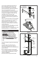
2. If the vent exit is on top of the stove
(Figure 1):
A. Place the appliance according to the
manufacturer’s instructions.
B. Drop a plumb bob to the center of the
appliance ue outlet and mark center point
on the ceiling, cut a square hole in the ceiling
for the Ceiling Support Firestop Spacer. Refer
to Table 1 for the dimensions of the hole.
C. Connect Pipe Adapter to stove: Attach
each section of pipe by pushing male and
female ends of pipe together and twisting
until pipe is in locked position.
D. When the pipe passes through the Ceiling
Support Firestop Spacer at ceiling, tighten
bolt and clamp around pipe.
E. Always maintain at least 1" clearance
from combustible materials. Where the
chimney passes through additional oors
and ceilings, always install a Ceiling Support
Firestop Spacer.
F. When the PelletVent enters the Attic, install
an Attic Insulation Shield around the vent
(Figures 1 & 3). This will prevent insulation
and debris from collecting near the vent pipe.
Use (4) wood screws to secure the base of the
Attic Insulation Shield to the framed opening.
Adjust the height of the Attic Insulation
Shield by sliding the top cylindrical shield
over the one from the base. Insure that the
top of the Shield is above the level of building
insulation. Secure the Shield in place with at
least two (2) sheet metal screws through the
side of the cylindrical shield. Attach collar
around the top of the Attic Insulation Shield.
G. After lining up for the hole in roof, using
the same method as 2.(B), cut either a round
or square hole in the roof. Always cut the
hole with the proper clearance to sides of
Flashing under the roong materials and nail
to the roof along the upper edge. Do not nail
across the lower edge. Seal all nail heads with
non-hardening waterproof sealant.
H. To nish, apply high-temperature non-
hardening RTV waterproof sealant where the
Storm Collar will meet the vent and Flashing;
slide Storm Collar down until it sets on the
Flashing, put the Cap on and twist to lock
(Figure 2).
3. If the ue exits on back of stove and an
interior installation is desired (Figure 3):
A. Place the appliance according to the
manufacturer’s instructions.
B. Connect and seal a Pipe Adapter to the
back of the stove and attach a Tee to Pipe
Adapter, align, push together and twist to
lock.
C. Continue to assemble pipe as described in
Step 2.
4. If the ue exit is on the back of stove, and
an exterior vertical installation is desired
Figure 4):
A. Place the appliance according to
manufacturer’s instructions.
B. Cut a square opening in the wall in
accordance with the dimensions in Table
1. The black portion of the Wall Thimble is