Venting System for Pellet, Corn, Oil, and Biofuel appliances.
A MAJOR CAUSE OF VENT RELATED FIRES IS FAILURE TO MAINTAIN REQUIRED CLEARANCES (AIR SPACES) TO COMBUSTIBLE MATERIALS. IT IS OF THE UTMOST IMPORTANCE THAT DOUBLE WALL PELLETVENT PRO BE INSTALLED ONLY IN ACCORDANCE WITH THESE INSTRUCTIONS. NOTE: Read through all of these instructions before beginning your installation. Failure to install as described in this instruction will void the manufacturer’s warranty, and may have an effect on your homeowner’s insurance and UL listing status.
For the most up-to-date installation instructions, see www.duravent.com CONTENTS PelletVent Pro Venting System for Pellet, Corn, Oil, and Biofuel appliances. Clearances, Vent Listing, Installation Notes, Lubricants & Gaskets . . . . 4 Sealants, Fuel Selection, Best Practices . . . . . . . . . . . . . . . . . . . . . . . . . . . 5 Tools Needed, Permits, General Installation Instructions . . . . . . . . . . . . . . .6 Installation into Masonry Fireplaces . . . . . . . . . . . . . . . . . . . . . . . . . .
CLEARANCES AND APPLICATIONS Dura-Vent’s PelletVent Pro is listed by Underwriters Laboratories as vent for listed appliances that burn oil, pellet, corn, and other biofuels. PelletVent Pro is also listed as a masonry reliner with the minimum clearance is 0” from vent to masonry, and 0” clearance from the masonry to nearby combustibles. Never fill any required clearance space with insulation or any other materials.
lubricate the new O-ring gasket. Replacement gaskets and silicone lubricants are available to order from the PVP catalog or our website at duravent.com. SEALANTS PelletVent Pro does not require additional sealant to be used at pipe joints, but in certain circumstances sealant may be used if desired.
corrosion to the system if left unchecked. Using pelletized fuel does not eliminate the need for inspection and cleaning. Lesser quality pellets create more soot accumulation and can clog venting sooner than the cleaner burning pellets.
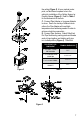
the ceiling (Figure 2). At your marked center point, cut and frame a square hole in the ceiling for installation of the Ceiling Support or Firestop Spacer (Figure 3). Refer to Table 1 for the dimensions of the hole. C. Connect Pipe Adapter or Increaser Adapter to stove: Due to the variety of different stove collars, the Pipe Adapter will need hightemperature non-hardening sealant in order to achieve a leak-free connection. . D. Connect Pipe Sections.
Figure 4 Figure 6 8 Figure 5 Figure 7
Pro pipe sections do not require any sealant; however in certain instances high temp silicone sealant may be used. Seal connection where the inner liners overlap for best results (Figure 5). Screws are not needed, but 1/4” screws can be used if desired, however, be sure you do not penetrate the inner liner. E. When the pipe passes through the Ceiling Support Firestop Spacer at ceiling, tighten bolt and clamp around pipe.
PELLET VENT PRO PIPE Figure 11 Figure 10 3. If the flue exits on back of stove and an interior installation is desired (Figure 10): A. Place the appliance according to the manufacturer’s instructions. B. Connect the Tee Adapter or combine Tee with Cleanout and Pipe Adapter then seal and secure the Pipe Adapter to the back of the stove. C. Continue to assemble Pipe Sections as described in Step 2. 4.
Figure 12 Connect the flexible hose with clamp to the exterior half of the Wall Thimble. Guide the flex through the opening in black interior half of Wall Thimble, gently pull the flex towards appliance (Figure 12), and if necessary trim excess flex to required length with snips. Secure flex to combustion air inlet of the stove with clamp provided. Only connect metal flex to the appliance; do not substitute or install plastic flex.
Figure 15 Figure 16 12 clearance from the pipe in order to make a safe installation. However, building insulation may be installed around the outside of the Wall Thimble. C. Connect a Pipe Adapter and Pipe Section together then seal connection to rear exhaust outlet. Attach a Single Tee with Clean out adapter or a Double Tee with Clean-Out Adapter, and proceed attaching Pipe Sections up the wall.
PELLET VENT PRO PIPE Figure 17 beyond the exterior wall after Horizontal Cap (c) Not less than 2 ft. (0.61m) from an is attached. If you are burning Corn you must adjacent building and not less than 7 use a Round Horizontal Cap. Pipe Sections ft. (2.1m) above grade when located exposed to exhaust gases between wall and adjacent to public walkways. Cap must have a Stainless Steel outer liner.
adapter or connector going into the ceiling support box. B. Visually inspect with a flashlight the condition of the interior of the chimney for cleanliness and structural integrity. All evidence of soot and creosote must be removed from the existing chimney system. If you doubt your ability to accomplish this, contact a certified chimney sweep. Do not use chemical cleaners, as these can possibly damage the inside of the chimney. Do any required maintenance on the existing chimney system at this time. C.
INSTALLATION INTO A MASONRY FIREPLACE 1. Have the masonry chimney inspected by a certified chimney sweep or installer to determine its structural condition. 2. Carefully read the pellet stove or insert installation instructions. 3. Measure and record the dimensions as shown in (Figure 18). 4. Use dimension “A” to determine total pipe requirements. Add 12 additional inches to ensure the termination is an adequate distance above the roofline. 5. The gross pipe required will be dimension “A” plus 12 inches.
Figure 23 Figure 25 Figure 24 16
to connect the Flex Pipe to the pipe on the appliance. It may be necessary to tie a line to the top section, to pull it back up later. 8. In making the connection at the appliance, configurations other than the one shown in (Figure 20) may be made. It may be necessary to contact the manufacturer of the unit to determine exactly what may or may not be done to make the correct connection. Some typical arrangements are shown in (Figures 21 and 22).
Figure 27 the offset down to opening in masonry. B. A Tee Section is installed at the bottom end of the vertical pipe (Figure 26). C. A Reduction Collar or a Trim Collar is required to go around the pipe section that passes through the masonry to give it a finished look. 3. It will be necessary to break out the masonry around the location of the pipe center line mark to a diameter of at least 4 inches for 3 inch pipe, and at least 5 inches in diameter for 4 inch pipe. 4.
Figure 28 Figure 29 Figure 30 Figure 31 19
Figure 32 Figure 33 Figure 34 20 members. 6. Run the Support Box through the roof as shown in (Figure 30), and place it so that the bottom of the Support Box protrudes at least 2 inches below the low side of your opening in the finished ceiling (Figure 31). Align the Support Box vertically and horizontally with a level. Temporarily tack the Support Box in place through the inside walls and into the roof sheathing. 7.
CLEANING AND MAINTENANCE 1. Have your system cleaned by a certified chimney sweep if you have doubts about your ability to clean it. Use a plastic or flexible steel brush. Do not use a stiff brush that will scratch the stainless steel liner of your system. 2. PelletVent Pro systems must be installed so that access is provided for inspection and cleaning. 3. The system should be inspected at least once every month during the heating season. 4. Do not use chemical cleaners. They can damage the vent pipe. 5.
M&G DuraVent Warranty M&G DuraVent, Inc. (“DuraVent”) provides this limited lifetime warranty for all of its products to the original purchaser, with the exception of Ventinox (lifetime), DuraBlack (five years) and all Termination Caps (five years). Subject to the limitations set forth below, DuraVent warrants that its products will be free from substantial defects in material or manufacturing, if properly installed, maintained and used.