
Install Instructions


9
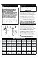
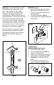
7. Add additional components to raise vent
level if desired (vent to be 12" above
grade or average snow level).
8. Remove gasket and install Bird Guard
into end of pipe. (Fig.11)
9. Install Poly Pro venting system to/from
termination to appliance.
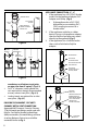
Figure 12
POSITIONED
HORIZONTALLY
POSITIONED
VERTICALLY
AIR INLET PIPE
OUTER COVER PLATE
APPLY BEAD OF SILICON SEALANT
AROUND FEMALE END OF PIPE TO
SEAL AGAINST EXTERIOR WALL PLATE
INTERIOR
WALL PLATE
EXTERIOR WALL PLATE
EXHAUST TIP
EXHAUST PIPE
Table 3 - Wall & Ceiling Penetration Sizing Table
VENT DIAMETER
Termination 2" 3" 4" 5" 6" 8"
CONCENTRIC
VERTICAL OR HORIZONTAL
4 ⁄"
105mm
5 ⁄"
130mm
6 ⁄"
155mm
N/A N/A N/A
TWIN PIPE HORIZONTAL
CLASS IIB
7 ⁄" x 2⁄"
187mm x
65mm
8 ⁄" x 3⁄"
212 x 85mm
9" x 4⁄"
228 x 100mm
N/A N/A N/A
TWIN PIPE HORIZONTAL
CLASS IIC (Framing Dimensions)
8" x 3"
200 x 77mm
8 ⁄" x 3⁄"
225 x 98mm
9 ⁄" x 4 ⁄"
238 x 112mm
N/A N/A N/A
SINGLE HORIZONTAL
CLASS IIB
2⁄"
65mm /
3 ⁄" "
85mm
4" "
100mm
N/A N/A N/A
SINGLE HORIZONTAL
CLASS IIC (Framing Dimensions)
3"
77mm
3 ⁄
98mm
4 ⁄
112mm
N/A N/A N/A
SINGLE WALL W/ LOCKING BAND
VERTICAL
3 ⁄" 4 ⁄" 5 ⁄" 6 ⁄" 7 ⁄" 9 ⁄"
SINGLE PIPE NO LOCKING BANDS
VERTICAL
3" 3 ⁄" 4 ⁄" 5 ⁄" 6 ⁄" 7 ⁄"
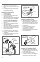
Horizontal Twin Pipe (Fig.12)
1. Locate penetration.
2. Cut or cut and frame hole. (Table 3)
3. Attach interior wall plate to inside wall.
4. Attach and seal exterior wall plate to
outside wall.
5. Slide pipes through outer plate.
6. Rotate pipes to slide pipe past keyway.