
Manual


9
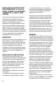
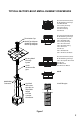
Figure 8
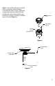
Figure 9
Connector to mount directly on the masonry
and provide clearance to the combustibles.
Refer to Figure 11.
Step 3. Secure the Flashing (705C) to the top
of the masonry chimney using a bead of non-
hardening sealant-adhesive. If the Flashing is
larger than the top of the chimney, then cut
and fold ashing as needed to t chimney.
See Figure 7.
Step 4. To determine the length of ex
required, measure from 3” above the top
of the Flashing down to the level of the
opening. Add to this measurement the
distance from the center of the chimney to
out through the wall. Cut a piece of 4-inch
ex to this length (the ex should already be
extended to its nominal length).
Step 5. Connect the 4-inch ex liner to the
Top Adapter (985K) using (3) sheet metal
screws. Refer to Figure 2.
Step 6. Feed the 4-inch ex liner through
the Flashing into the chimney. Continue to
feed the liner out through the opening in the
masonry wall.
Step 7. Secure the Top Adapter to the
Flashing. Use (3) sheet metal screws through
the side of the adapter into the ange on the
Flashing, as shown in Figure 8. Twist lock the
Termination Cap (980 or 991) on to the Top
Adapter.
Step 8. Attach the ex to the Retro
Connector. Use (3) sheet metal screws to
attach the ex liner to the Connector. See
Figure 9. Mount the Retro Connector to the
masonry wall using masonry bolts. Re-
drill larger holes on connector as needed.
Be careful to insure that the connector is
centered in the opening and the mounting
holes line up with the masonry wall.
6” diameter
opening in
masonry wall
(3)
Sheet
Metal
Screws
Highwind Termination
Cap
Flashing
Standard
Termination
Cap
Top Adapter
Retro Connector
(3) masonry bolts (not
included)