
Installation

23
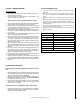
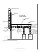
X min. = EXPANSION + 3 [inch]
EXPANSION = (length[feet]/100)x(
∆T[°F]/100)
Operating Temp. [°F] Max distance with one Adjustable length [feet]
200 200
300 133
400 100
500 80
800 50
1000 40
1200 33
1400 29
Table 15 : Maximum run with Adjustable length between two fixed points
ADJUSTABLE LENGTH
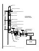
1. The adjustable length (LA) is used for two functions, one is to make
odd lengths and the other to serve as an expansion joint.
2. The adjustable length may be used when internal pressure do not
exceed 6” water column or in well ventilated areas. See Figure 66
for good positioning of the adjustable length.
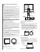
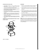
3. The adjustable length assembly includes a sliding inner section, two
containing rings, one compression band, a graphite packing gasket,
an insulation band (DIS only) and a telescopic outer casing. There
is a tool supplied with this assembly. (see Figure 67).
4. For proper installation, the adjustable length must have adequate
overlap and sufficient allowance for thermal expansion. (see Figure
56 - Adjustable length (LA), and table 15).
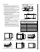
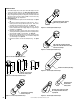
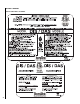
5. Installation steps (see Figure 57):
a. Adjust the length of the chimney as required. If outer casing
or inner flue are too long, they may be cut to length. You must
keep the overlap of the outer casing to at least 1”. You are only
authorised to cut on the outer casing section attached to the
female coupling. See Figure 52.
b. Move up the sliding section of the outer wall to access inner
wall. See Figure 53.
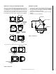
c. Tighten the compression band so that the graphite packing is
firmly registered against the inner flue. See Figure 54.
d. Tighten all the bolts of the containing ring. For each bolt, use
the supplied tool as a guide between the two containing rings
(see Figure 55).
e. Fill the gap between the inner flue and outer casing with the
supplied insulation band. See Figure 56 (DIS only).
f. Move down the sliding section of the outer wall to the flange of
the female coupling and install the locking band as described in
section A: Chimney and fitting joint assembly. See Figure 57.
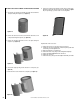
Figure 58 - Adjustable length
Figure 52 - Adjustable length, INSTALLATION STEP A
Desired length
Figure 55 - Adjustable length, INSTALLATION STEP D
Supplied tool
Desired length
Move outer casing
Figure 53 - Adjustable length, INSTALLATION STEP B
Figure 56 - Adjustable length, INSTALLATION STEP E
Figure 57 - Adjustable length, INSTALLATION STEP F
Figure 54 - Adjustable length, INSTALLATION STEP C
NOTE: DIAGRAMS & ILLUSTRATIONS ARE NOT TO SCALE.
Wrench
Compression band
Insulation band (DIS only)
Graphite packing
Containing ring
Telescopic
outer casing
1” Min.
overlap
X Min.