
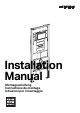
Installation Sheet


4
D54386-001 © 04-2012
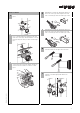
Tank and carrier installation
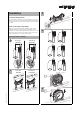
1
Locate carrier supporting studs and reinforce with
additional nails. Ensure rough-in for the carrier is
plumb and square. Wall framework must be affixed
to the floor and ceiling for maximum support.
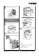
2
Position carrier unit in the prepared opening.
Carrier face plate must be flush with the front of the
surrounding studs so that maximum support for
the wall sheeting (applied later) will be
accomplished. With carrier still in place, mark all
anchor and bolt hole locations on sole plate and
studs. Mark location for the 3" DWV discharge
pipe.
3
Pull out carrier from framework and drill six (6) pilot
holes (3/16") for the supplied lag screws where
marked on sole plate. Also drill six (6) bolt holes (5/
16") where marked on both studs. Use hole saw
and bore a 4" hole through sole plate and floor for
the discharge stop out pipe.
4
Install 3" DWV waste pipe through floor and
connect to waste line (i.e. PVC, copper, cast iron).
5
Set carrier unit sideways back into framework and
bolt in place with hardware provided.
6
Complete waste elbow connection with 3" DWV
shielded coupling (D - provided) to waste pipe.
7
Install two (2) 1/2" x 6" fixture support rods with
plastic sleeves (A), yellow pipe caps (B) and mud
guard (C) for protection during wall surface
construction.
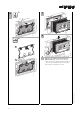
0
°
−
4
5
°
0
°
−
4
5
°
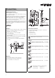
For finishing the installation of bowl and actuator
plate see detailed instructions.
19
3
/4
"
12"–16"
F. F.
47"–51"
C
A
B
D
5
/16
"
5
/16
"
A
Install
1
/2
" rods with plastic sleeves,
B
pipe plugs and
C
mud guard during the rough-in installation
D
Complete waste elbow connection with 3" DWV
shielded coupling (D - provided) to waste pipe.