71/173 Operating Manual
All rights reserved. Property of Dürkopp Adler AG and protected by copyright. Any reuse of these contents, including extracts, is prohibited without the written approval in advance of Dürkopp Adler AG.
Table of contents 1 About this operating manual ................................. 3 1.1 1.2 1.3 ters 1.4 1.5 1.5.1 1.5.2 Scope of application of the operating manual........... 3 For whom is this operating manual intended? .......... 3 Representational conventions - Symbols and charac4 Other documents ...................................................... 4 Liability...................................................................... 5 Transportation.....................................................
Table of contents 5.12 5.13 5.14 5.15 5.15.1 5.16 5.16.1 5.17 2 Keypad on the machine arm................................... 42 Operating the controller .......................................... 43 Sewing .................................................................... 43 Maintenance ........................................................... 45 Cleaning work ......................................................... 45 Checking the pneumatic system............................. 46 Oil lubrication ....
About this operating manual 1 About this operating manual The operating manual for the special sewing machine 171/173 was compiled with the utmost care. It contains information and notes in order to make long-term and reliable operation possible. Should you notice any discrepancies or if you have improvement requests, then we would be glad to receive your feedback. Please regard the operating manual as part of the product and keep it in a safe place where it can be easily accessed.
About this operating manual 1.3 Representational conventions - Symbols and characters Different information is depicted or highlighted in this operating manual by the following characters for easier and quicker understanding: Symbol/character Meaning • Lists are identified by bullet points. 1. 2. ... Instructions are numbered and have to be performed in the specified order. References to further information in this operating manual or other documents are identified by this symbol.
About this operating manual 1.5 Liability All information and notes in this operating manual have been compiled in accordance with the latest technology and the applicable standards and regulations. The manufacturer cannot be held liable for any damage due to: • • • • • • Damage during transport Failure to observe the operating manual Improper use Unauthorized modifications to the machine The deployment of untrained personnel Using unapproved spare parts 1.5.
About this operating manual Only authorized/trained persons may work on the machine. The manufacturer will not be held liable for damage resulting from improper use. WARNING Danger due to high voltage, crushing and sharp objects. Improper use can result in injuries. Please follow all instructions in the manual. ATTENTION Improper use could result in material damage. Please follow all instructions in the manual. 6 Operating manual 171/173 Version 01.
Performance description 2 Performance description The Dürkopp Adler 171 and 173 are, respectively, single- and twin-needle double chain stitch crossline sewing machines for linear seams, using stitch type 401. 2.
Performance description 2.2 Declaration of conformity The machine complies with the European regulations specified in the declaration of conformity or in the installation declaration. 2.3 Technical data Noise emission Workspace-specific emission value as per DIN EN ISO 10821 for class 171: LpA = 79,4 dB(A); KpA = 0,58 dB(A). Workspace-specific emission value as per DIN EN ISO 10821 for class 173: LpA = 79,0 dB(A); KpA = 1,33 dB(A).
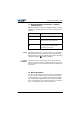
Performance description Features 171141621 173141610 173141621 550-2-2 550-15-5 Model 173 171131610 Model 171 Max. number of stitches [per min.] 6,600 6,000 6,000 6,000 5,500 6,000 Number of stitches on delivery [per min.] 6,600 5,800 5,800 5,800 5,500 5,500 Number of stitches, use of hemming system [per min.] 5,500 - Max. number of stitches as twin-needle machine (depending on E-No.) [per min.
Performance description 173141610 173141621 550-2-2 Twin-needle kit to convert a single-needle into a twin-needle double chain stitch machine (For installation in 171-141621 without thread cutter) 0175 590074 Parts set to build a 550-2-2 (Only in combination with twin-needle kit 0175 590074 and 173-E204/5) 0550 590344 Parts set to build a 550-15-5 (Only in combination with frame 0550 400224 [short table plate with sep.
Performance description Model 171 171141621 173141610 173141621 550-2-2 550-15-5 Model 173 171131610 Material number Edge stop right, swivels upwards, secured to the cloth pressure bar, adjustable width 0 - 40 mm (cannot be used for E1) N900 023421 Edge stop right and left, swivels upwards, secured to the cloth pressure bar connector, adjustable width 0 - 40 mm N900 060034 Edge stop right, swivels upwards, secured to the cloth pressure bar, adjustable width 0 - 40 mm N900 023
Performance description Model 171 171141621 173141610 173141621 550-2-2 550-15-5 Model 173 171131610 Material number Sewing lamp attachment set 0APP 001041 LED sewing lamp k 0271 590044 Integrated LED sewing lamps 0171 590054 Sewing lamp transformer (for both sewing lamps) 9850 001089 Steel carrier roller 1 mm, pyramid-tooth cut, 9 mm wide 0933 005736 Steel carrier roller 1 mm, pyramid-tooth cut, 15 mm wide 0933 005737
Safety instructions 3 Safety instructions This section contains basic instructions for your safety. Read the instructions carefully before setting up, programming, maintaining or operating the machine. Make sure to follow the information included in the safety instructions. Failure to do this can result in serious injury and damage to the machine. 3.1 General safety instructions The machine may only be used as described in this manual.
Safety instructions Operator's Observe the country-specific safety and accident prevention obligations regulations and the legal regulations concerning industrial safety and the protection of the environment. All warnings and safety signs on the machine must always be in legible condition and may not be removed. Missing or damaged labels must be replaced immediately. Requirements to The machine may only be set up by qualified specialists.
Safety instructions 3.2 Signal words and symbols used in safety instructions The safety instruction text is surrounded by colored bars. Signal words specify the severity of a danger: Signal word Degree of severity DANGER Resulting in death or serious injury. WARNING Death or serious injury possible. CAUTION Moderate to minor injuries possible. ATTENTION Material damage possible.
Safety instructions Examples of the layout of the safety instructions in the text: DANGER Type and source of the danger Consequences in the event of noncompliance Measures for avoiding the danger This is what a hazard note looks like for a hazard that will result in serious injury or even death if not complied with.
Device description 4 Device description Fig. 1: Complete overview ① ⑧ ② ⑦ ③ ⑥ ⑤ ④ (1) - Thread tensioner for needle thread (2) - Adjusting wheel for sewing foot pressure (3) - Thread lever with thread regulator (4) - Needle bar with needle (5) - Adjusting wheel for the 2nd stitch length (stitch condensing) (6) - Adjusting wheel for normal stitch length for sewing (7) - Thread tensioner for looper thread (8) - Handwheel Operating manual 171/173 Version 01.
Device description 18 Operating manual 171/173 Version 01.
Operation 5 Operation 5.1 Switching the power supply on and off The controller is located under the table plate. The main switch (1) on the controller regulates the power supply. Fig. 2: Switching the power supply on and off ① ② (1) - Main power switch (2) - Indicator lamp on the controller To switch on the power: 1. Press the main switch (1) down to position I. The indicator lamp (2) lights up. To switch off the power: 1. Press the main switch (1) up to position 0. The indicator lamp (2) goes off.
Operation 5.2 Inserting and replacing the needle WARNING Risk of injury from the needle point and moving parts. Switch off the sewing machine before replacing the needle. Do not touch the needle point. Sequence After changing to needles with strength 100 or greater, have a technician adjust the needle evasive movement of the looper (ellipse width). The correct settings are described in the Service manual. Fig.
Operation 5.3 Threading the needle thread WARNING Risk of injury from the needle point and moving parts. Switch off the sewing machine before inserting the thread. Fig. 4: Fit the needle thread reel. ① ② (1) - Guide on unwinding bracket (2) - Reel stand 1. Fit the thread reel on the left plate of the reel stand (2). 2. Insert the thread from the back to the front through the first hole and then in a wavelike manner through the next two holes of the guide on the unwinding bracket (1).
Operation Fig. 6: Threading the needle thread - Part 1 ① ② ③ ⑥ ④ ⑤ (1) - Thread guide (2) - Thread guide (3) - Needle thread tensioner (4) - Thread guide (5) - Thread puller (6) - Tensioner opener 3. Feed the thread through the thread guide (1) from above downwards. 4. Guide the thread around the back of the thread guide (1) and from the rear to the front through the bottom hole. 5. Feed the thread from above downwards through the thread guide (2) to the needle thread tensioner (3). 6.
Operation Fig. 7: Threading the needle thread - Part 2 (a) (b) ① ② ③ ⑤ ④ ⑥ (1) - Deflector (2) - Thread regulator (3) - Thread lever (4) - Thread guide, machine head (5) - Thread guide, needle bar (6) - Needle eye 9. Feed the thread from the right to the left through the deflector (1). 10. Insert the thread from right to left through the thread regulator (2) and thread lever (3): • For tight/normal seams ( pg.
Operation 5.4 Threading the looper thread WARNING Risk of injury from moving parts. Switch the sewing machine off before threading. Fig. 8: Fitting the looper thread reel ① ② (1) - Guide on unwinding bracket (2) - Reel stand 1. Fit the thread reel on the right plate of the reel stand (2). 2. Insert the thread from the back to the front through the first hole and then in a wavelike manner through the next two holes of the guide on the unwinding bracket (1).
Operation Fig. 10: Threading the looper thread - Part 1 ① ② ③ ④ ⑤ ⑥ ⑦ (1) - Thread guide (2) - Thread guide (3) - Looper thread tensioner (4) - Thread guide (5) - Tensioner opener (6) - Thread puller (7) - Thread groove 3. Feed the thread through the thread guide (1) from above downwards. 4. Guide the thread around the back of the thread guide (1) and from the rear to the front through the bottom hole. 5.
Operation Fig. 11: Threading the looper thread - Part 2 ① ② ③ ④ (1) - Looper hole (2) - Looper hole (3) - Thread down-holder ⑤ (4) - Hole, looper thread guide (5) - Hole, looper thread guide 9. Remove the cover plates to the right and left of the throat plate. 10. Lift the thread down-holder (3) from its latching. 11. Insert the thread from the right to the left through holes (5) and (4) of the looper thread guide. 12. Turn the handwheel until the looper hole (2) is accessible. 13.
Operation 5.5 Threading twin-needle machines WARNING Risk of injury from the needle point and moving parts. Switch off the sewing machine before threading. Twin-needle machines have a second tensioning wheel and a second thread guide on the machine arm, to accommodate both the needle thread and the looper thread. Fig.
Operation 5.6 Adjusting the thread tension and quantity 5.6.1 Thread types and stitch formation Both the thread tension and the thread quantity for stitch formation must be adjusted to the desired seam appearance for both needle thread and looper thread. A differentiation is made between 3 seam types: • Tight seams (1) • Normal seams (2) • Highly elastic seams (balloon stitch) (3) Fig. 13: Different seam types ① ② ③ (1) - Tight seam (2) - Normal seam (3) - Highly elastic seam (balloon stitch) 5.6.
Operation Fig. 14: Adjusting the thread tensions ① ② (1) - Adjusting wheel, needle thread tension (2) - Adjusting wheel, looper thread tension Adjusting the thread tension • To increase the tension: Turn the adjusting wheel (1 or 2) for the relevant thread clockwise. • To reduce the tension: Turn the adjusting wheel (1 or 2) for the relevant thread counterclockwise. 5.6.3 Adjusting the needle thread quantity WARNING Risk of injury from moving parts.
Operation Fig. 15: Setting the thread regulator (a) ① ② ③ ④ (b) ① ② ④ ③ (1) - Fastening screws (2) - Thread regulator (3) - Hole of the thread lever (4) - Thread regulator: Lower bar Correct setting • Less elastic threads: The hole (3) of the thread lever is visible in the thread lever's bottom position just above the lower bar (4) of the thread regulator: position (a).
Operation 5.6.4 Adjusting the looper thread quantity WARNING Risk of injury from moving parts. Switch the sewing machine off before setting the looper thread take-up. The looper thread take-up adjusts the looper thread quantity to the relevant set stitch length so that the stitch pull is optimal for every length and also for stitch condensing. The looper thread take-up can be adjusted continuously on a scale from 0 to 5.
Operation Fig. 16: Adjusting the looper thread take-up ① ② ③ ④ ⑤ ⑥ (1) - Thread down-holder (2) - Thread down-holder: Lower bar (3) - Looper thread take-up: Holes for thread guide (4) - Looper thread take-up edge: Scale reading point (5) - Looper thread take-up (6) - Fastening screw Adjusting the looper thread take-up 1. Tilt the upper part of the machine backwards. 2. Loosen the fastening screws (6). 3. Move the looper thread take-up (5): • Tighter seam: Move front edge (4) in the direction of 0.
Operation 5.7 Adjusting the stitch length/bottom feed Bottom feed and stitch length are adapted to one another. When adjusting the stitch length using the adjusting wheels on the machine column, the length of the bottom feed is automatically adapted. 5.7.1 Adjusting the stitch length The stitch length can be adjusted by turning the adjusting wheel (2) continuously between 1 and 4 mm. The adjusting mark (1) on the left of the wheel indicates the stitch length selected. Fig.
Operation Adjusting the stitch length on the 171-131610 The submodel 171-131610 does not have adjusting wheels for the stitch length. Here, the stitch length is adjusted on the machine underside. Fig. 18: Adjusting the bottom feed/stitch length on the 171-131610 back front ① (1) - Fastening screw ② (2) - Stitch length lever WARNING Risk of injury from moving parts. Switch off the sewing machine before tilting the machine upper part back and adjusting the stitch length on the 171-131610.
Operation 5.7.2 Adjusting the stitch condensing For machines with pushbuttons on the machine arm ( 5.12 Keypad on the machine arm, pg. 42) it is possible to switch over to stitch condensing while sewing. The stitch length for stitch condensing can be adjusted by turning the adjusting wheel (2) continuously between 1 and 4 mm. The adjusting mark (1) on the left of the wheel indicates the stitch length selected.
Operation 5.8 Adjusting the top feed On the 173, there is another roller top feed in addition to the bottom feed. The top feed can be set independently of the bottom feed and can thus be adjusted individually to the feed behavior of the relevant sewing material. When sewing the stitch condensing at the start and end of the seam, the roller top feed is automatically adjusted to the shortened bottom feed. 5.8.
Operation 5.8.2 Adjusting the contact pressure of the carrier roller WARNING Risk of crushing from moving parts. Switch off the sewing machine before adjusting the contact pressure of the carrier roller. The contact pressure of the carrier roller must be adapted to the relevant sewing material. Correct setting The sewing material does not slip and is fed through correctly. Fig.
Operation 5.8.3 Lifting the carrier roller To sew corners or radii, the carrier roller (3) can be lifted a little using the button (2). Using the hand lever (1), the carrier roller (3) can be raised completely out of the sewing area, e.g., if only the bottom feed is to be used for sewing. Fig. 22: Lifting the carrier roller ① ② ③ (1) - Hand lever (2) - Button for lifting the roller (3) - Carrier roller Lifting the carrier roller briefly: 1. Press the bottom-most button (2) on the keypad.
Operation 5.9 Setting the sewing foot pressure The adjusting wheel (1) on the machine head determines the pressure of the sewing foot on the sewing material. The pressure can be adjusted continuously by turning the wheel. Correct setting The sewing material does not slip and is fed through correctly. The correct pressure depends on the sewing material.
Operation 5.10 Lifting the sewing foot To insert or feed the sewing material, the sewing foot - depending on the machine equipment - is lifted either mechanically with the knee lever or electromagnetically with the food pedal. Fig. 24: Lifting the sewing foot ① ② (1) - Knee lever (2) - Pedal Lifting the sewing foot with the knee lever 1. Push the knee lever (1) to the right. The sewing foot is lifted and remains up as long as pressure is maintained on the knee lever.
Operation 5.11 Locking the sewing foot in the upper position The pushbutton on the machine head can be used to hold the lifted sewing foot in the upper position. Fig. 25: Locking the sewing foot in the upper position ① (1) - Locking pushbutton Locking the sewing foot in the upper position 1. Lift the sewing foot with the knee lever or the pedal. ( 5.10 Lifting the sewing foot, pg. 40) 2. Press the locking pushbutton (1). 3. Release the knee lever or pedal.
Operation 5.12 Keypad on the machine arm Depending on the equipment, there is a keypad located on the machine arm to quickly call up various functions. Fig. 26: Keypad on the machine arm ② ① (1) - Keypad Element (2) - Indicator lamp, power supply Function/meaning Inverts stitch condensing Reverses the general setting for automatic stitch condensing at the start and end of the seam: If stitch condensing is generally switched on, it is suppressed for the next stitch condensing.
Operation 5.13 Operating the controller The machine is operated using the DAC eco or DAC classic controller. Operation of the controller is described in its own operating manual. The operating manual for the DAC eco or DAC classic is provided in the accessory pack delivered with the controller. The operating manual is also available in the download area at www.duerkopp-adler.com 5.14 Sewing WARNING Risk of injury from the needle tip on unintentional start of sewing.
Operation START OF SEWING Initial position 1. Switch on the sewing machine. 2. Pedal position 0: Machine stationary, needles up, sewing foot down. Positioning the sewing material 1. Press the foot pedal half-way back to pedal position -1: The sewing foot is raised. 2. Push the sewing material into the initial position. 3. Release the foot pedal to pedal position 0. The sewing foot lowers onto the sewing material. To start sewing 1.
Operation 5.15 Maintenance This section describes simple maintenance work that needs to be carried out on a regular basis. This maintenance work can be carried out by the operating personnel. Advanced maintenance work must only be carried out by qualified specialists. Advanced maintenance work is described in the Service manual. 5.15.1 Cleaning work WARNING Risk of injury due to flying particles. Switch off the machine at the main power switch before starting any cleaning work.
Operation Cleaning steps 1. Switch off the power supply at the main switch. 2. Remove any sewing dust and thread remains using a compressed-air pistol or a brush. 3. Remove any sewing dust and cutoffs from the oil pan. ATTENTION Possible damage to the paintwork from solvent-based cleaners. Solvent-based cleaners damage the paintwork of the machine. Use only solvent-free substances when wiping down the machine. 5.16 Checking the pneumatic system Fig.
Operation Water condensation accumulates in the water separator of the maintenance unit. Fig. 29: Water level in the maintenance unit 6 4 8 2 10 0 1 2 3 (1) - Filter element (2) - Water separator (3) - Drain screw Checking the water level: 1. Check the water level every day. Important: The condensation water must not rise to the level of the filter element (1). Drain water as required: 1. Switch off the sewing machine at the main switch. 2. Place the collection tray under the drain screw (3). 3.
Operation 5.16.1 Oil lubrication WARNING Skin injuries due to contact with oil. Oil can cause a rash if it comes into contact with the skin. Avoid any skin contact with the oil. If oil gets on your skin, wash the affected skin areas thoroughly. ENVIRONMENTAL PROTECTION Risk of environmental damage from oil. Oil is a pollutant and must not enter the sewage system or the soil. Collect waste oil carefully and dispose of it and oily machine parts in accordance with the applicable statutory regulations.
Operation Lubrication of the upper part of the machine Fig. 30: Lubrication of the upper part of the machine ① ② ③ (1) - Refill opening (2) - Maximum level marking (3) - Minimum level marking Checking the oil level 1. Check the oil level indicator every day. Correct setting The oil level must always be between the minimum level marking (3) and the maximum level marking (2). Topping up with oil Pour in oil through the refill opening (1) as required: 1. Switch off the sewing machine at the main switch. 2.
Operation Looper lubrication Check the oil level for looper lubrication approx. once every week. Fig. 31: Looper lubrication ① ② ③ ④ (1) - Locking screw (2) - Oil reservoir (3) - Maximum level marking (4) - Minimum level marking Checking the oil level 1. Switch off the sewing machine at the main switch. 2. Tilt the upper part of the machine back through 90°. 3. Check the quantity of oil in the reservoir (2).
Operation 5.17 Customer service Contacts for repair in the event of damage to the machine: Dürkopp Adler AG Potsdamer Str. 190 33719 Bielefeld, Germany Tel. +49 (0) 180 5 383 756 Fax +49 (0) 521 925 2594 Email: service@duerkopp-adler.com Internet: www.duerkopp-adler.com Operating manual 171/173 Version 01.
Operation 52 Operating manual 171/173 Version 01.
Set-up 6 Set-up WARNING Risk of injury. The machine may only be set up by trained specialists. Wear safety gloves and safety shoes when unpacking and setting up. 6.1 Checking the scope of delivery Important: The scope of delivery depends on your specific order. 1. Prior to set-up, check that all parts are present. Fig. 32: Example of the scope of delivery ⑨ ① ② ⑧ ③ ④ ⑤ (1) - Machine upper section (2) - Table plate (3) - Drawer (4) - Frame (5) - Pedal Operating manual 171/173 Version 01.
Set-up Maximum delivery scope: • Upper section of the machine (1) with sewing drive • Table plate (2) • Oil pan (not shown) - in the accessory pack • Drawer (3) • Frame (4) • Pedal (5) with rod • Setpoint device (6) with rod • Pneumatic maintenance unit (7) • Controller (8) • Control panel for DAC classic (not shown) • Reel stand with unwinding bracket (9) - in the accessory pack • Small parts in an accessory pack 6.
Set-up 6.3 Fitting the frame components Fig. 33: Fitting the frame components ① ② ③ ⑧ ④ ⑧ ⑤ ⑥ ⑦ ⑤ (1) - Head sections (2) - Oil can holder (3) - Frame bars (4) - Cross bars (5) - Frame feet (6) - Foot struts (7) - Cross strut (8) - Fastening screws 1. Screw the cross bars (4) onto the frame bars (3). 2. Screw the cross strut (7) onto the foot struts (6). 3. Screw the head sections (1) onto the frame bars (3). 4. Push all 4 frame feet (5) onto the foot struts (6). 5.
Set-up 6.4 Completing the table plate The table plate belongs to the optional delivery scope. Drawings are provided in 9 Appendix, pg. 77 to allow you to independently assemble a table plate. Fig. 34: Completing the table plate ① ② ⑥ ④ ③ (1) - Upper section support (only on 171) (2) - Rubber mounts (3) - Drawer ⑤ (4) - Cable duct (5) - Oil pan (6) - Corners Only on 171: 1. Insert the upper section support (1) in the hole of the table plate. 2. Fit the rubber mounts (2) into the recesses. 3.
Set-up 6.5 Fastening the table plate to the frame 1. Secure the table plate with wood screws (B8 x 35) onto the frame, in accordance with the dimensions on the diagram. Fig. 35: Dimensions for fastening the table plate to the frame Operating manual 171/173 Version 01.
Set-up 6.5.1 Installing the reel stand Fig. 36: Installing the reel stand ① ② ③ ④ (1) - Reel stand (2) - Unwinding bracket (3) - Thread reel holder (4) - Hole 1. Insert the reel stand (1) in the hole (4). 2. Fasten the reel stand (1) with nut and washer. 3. Screw the thread reel holder (3) and the unwinding bracket (2) onto the reel stand (1) so that they are precisely parallel to one another. 58 Operating manual 171/173 Version 01.
Set-up 6.6 Setting the working height The working height can be adjusted continuously between 750 and 900 mm (clearance between the floor and upper edge of the table plate). Fig. 37: Setting the working height ① ① (1) - Screws 1. Loosen all four screws (1) on the head sections. 2. Set the table plate to the desired height. Important: Pull out or push in the table plate evenly at both sides to prevent it from jamming. 3. Tighten the screws (1) on the head sections.
Set-up 6.7 Fitting the machine upper section WARNING Risk of crushing. The machine upper section is heavy. Take care not to jam your hands when fitting. This especially applies when fitting the hinge upper parts into the rubber inlays. Fig. 38: Fitting the machine upper section ① ③ ② (1) - Protective bar (2) - Hinge upper parts (3) - Support screws 1. Insert the machine upper section at a 45° angle from above with the hinge upper parts (2) in the rubber inlays. 2.
Set-up 6.8 Fitting the controller Fig. 39: Fitting the controller ① ② ③ (1) - Strain relief (2) - Screw holder (3) - Control 1. Screw the control (3) onto the 4 screw holders (2) under the table plate. 2. Clamp the power cable of the control into the strain relief mechanism (1). 3. Screw the strain relief mechanism (1) under the table plate. Operating manual 171/173 Version 01.
Set-up 6.9 Fitting the control panel for the controller For machines with the DAC classic controller, the OP 1000 control panel must be fitted. Fig. 40: Fitting the control panel - Part 1 ② ③ ④ ⑤ ① (1) - Handwheel (2) - Handwheel cover (3) - Arm cover (4) - Control panel bracket (5) - Control panel 1. Loosen the 3 fastening screws of the arm cover (3) and remove the arm cover (3). 2. Remove the handwheel (1) and handwheel cover (2). 3.
Set-up Fig. 42: Laying the control panel cable Cable guide 171 Cable guide 173 ⑦ (7) - Cable inlet Laying the control panel cable 6. Laying the cable behind the rear of the arm cover. Important: Note the different cable inlets (7) of the 171 and 173. 7. Guide the cable down under the handwheel cover. 8. Feed the cable through the table plate cutout downwards to the controller. Important: Lay and secure the cable such that it does not come into contact with any moving parts. 9.
Set-up 6.10 Fitting the pedal and setpoint device Fig. 43: Fitting the pedal and setpoint device ① ② ③ ⑥ ④ ⑤ (1) - Bracket (2) - Setpoint device (3) - Screw (4) - Pedal rod (5) - Pedal (6) - Cross strut 1. Place the pedal (5) on the cross strut (6) and align it in such a way that the middle of the pedal is under the needle. The cross strut has elongated holes to allow alignment of the pedal. 2. Screw the pedal (5) firmly onto the cross strut (6). 3. Screw the setpoint device (2) onto the bracket (1).
Set-up 6.11 Fitting the knee lever The machine has a mechanical knee lever, depending on the submodel and equipment. Fig. 44: Fitting the mechanical knee lever 3 1 2 (1) - Knee lever rod 1. 2. 3. 4. (2) - Hole in the oil pan (3) - Transmission rod Tilt the upper part of the machine backwards. Fit the transmission rod (3) in the oil pan. Screw the knee lever (1) rods together. Guide the rod (1) through the hole in the oil pan (2) and connect it to the transmission rod (3).
Set-up 6.12 Fitting the oil return line The oil return line collects the oil that runs into the oil pan and returns it via a pump to the oil circuit. Fig. 45: Fitting the oil return line ③ ① ② (1) - Oil hose (2) - Suction filter (3) - Clamp 1. Tilt the upper part of the machine backwards. 2. Wrap the suction filter (2) with its felt and secure to the oil plate using the clamp (3). 3. Important: Lay and secure the oil hose (2) such that it does not come into contact with any moving parts. 4.
Set-up 6.13 Electrical connection DANGER Danger to life due to electric shock. The machine may only be connected by trained electrical specialists. Disconnect the power plug before carrying out work on the electrical equipment. Make sure the power plug cannot be unintentionally reinserted. The voltage on the type plate of the sewing drive must correspond to the mains voltage. 6.13.
Set-up 6.13.3 Establishing equipotential bonding The earthing cable conducts away any static charging to ground. DANGER Danger to life due to electric shock. Disconnect the power plug before establishing equipotential bonding. Make sure the power plug cannot be unintentionally reinserted. Fig. 46: Establishing equipotential bonding ① ① ② ③ (1) - Connection point on the machine base plate (2) - Earthing cable (3) - Connection point on the controller 1.
Set-up 6.14 Pneumatic connection 6.14.1 Fitting the maintenance unit The pneumatic connection package is available under order number 0797 003031. It consists of: • System connection hose (length 5 m, diameter 9 mm) Hose connectors and hose clamps Coupling socket and coupling plug • • Correct setting The system pressure for the pneumatic unit is 8 - 10 bar. ATTENTION Machine damage possible due to incorrect pressure. Incorrect pressure can cause damage to the machine.
Set-up 6.14.2 Setting the operating pressure Correct setting The operating pressure for the pneumatic unit is 6 bar. ATTENTION Machine damage possible due to incorrect pressure. Incorrect pressure can cause damage to the machine. Make sure that the operating pressure is set correctly before putting the machine into operation. Fig. 48: Setting the operating pressure 1 6 4 8 2 10 2 0 (1) - Turning handle (2) - Pressure indicator 1. Pull the turning handle (1) up. 2.
Set-up 6.16 Sewing test Carry out a sewing test before starting up the machine. Adjust the machine to the requirements of the sewing material. To do this, read the corresponding sections in Chapter 5 Operation. Read the corresponding section of the Service manual in order to make adjustments to the machine if the sewing results do not conform the to the requirements. WARNING Risk of injury from the needle point and moving parts.
Set-up 72 Operating manual 171/173 Version 01.
Decommissioning 7 Decommissioning A number of activities must be performed if the machine is to be shut down for a longer period of time or completely decommissioned. WARNING Risk of injury due to a lack of care. A lack of care or a lack of sufficient technical knowledge when decommissioning the machine can result in serious injuries. ONLY clean the machine when it is switched off. Avoid contact with oil residues. Allow ONLY trained personnel to disconnect the machine.
Decommissioning 74 Operating manual 171/173 Version 01.
Disposal 8 Disposal The machine must not be disposed of in the normal household waste. The machine must be disposed of in an appropriate and correct manner according to the national regulations. ENVIRONMENTAL PROTECTION Risk of environmental damage due to incorrect oil disposal. Incorrect disposal of old oil can result in severe environmental damage. ALWAYS observe the legally prescribed regulations for disposal of oil.
Disposal 76 Operating manual 171/173 Version 01.
9 Appendix Dimensions for manufacturing a table plate
Appendix 78 Operating manual 171/173 Version 01.
Appendix Operating manual 171/173 Version 01.
Appendix 80 Operating manual 171/173 Version 01.
Subject to design changes - Printed in Germany - © Dürkopp Adler AG - Original Instructions - 0791 171740 EN - 01.0 - 01/2016 DÜRKOPP ADLER AG Potsdamer Str. 190 33719 Bielefeld Germany Phone +49 (0) 521 925 00 E-mail: service@duerkopp-adler.com www.duerkopp-adler.