367 Anbauanleitung für Bausatz 0367 595144 Instructions for fitting for kit 0367 595144 Pneumatische Fußlüftung D Sewing foot lift with pedal GB Postfach 17 03 51, D-33703 Bielefeld • Potsdamer Straße 190, D-33719 Bielefeld Telefon +49 (0) 5 21 / 9 25-00 • Telefax +49 (0) 5 21 / 9 25 24 35 • www.duerkopp-adler.com Ausgabe / Edition: 04/2010 Änderungsindex Rev. index: 01.0 Printed in Federal Republic of Germany Teile-Nr./Part.-No.
Vorwort Diese Anleitung soll erleichtern, die Maschine kennenzulernen und ihre bestimmungsmäßigen Einsatzmöglichkeiten zu nutzen. Die Betriebsanleitung enthält wichtige Hinweise, die Maschine sicher, sachgerecht und wirtschaftlich zu betreiben. Ihre Beachtung hilft, Gefahren zu vermeiden, Reparaturkosten und Ausfallzeiten zu vermindern und die Zuverlässigkeit und die Lebensdauer der Maschine zu erhöhen.
Allgemeine Sicherheitshinweise Die Nichteinhaltung folgender Sicherheitshinweise kann zu körperlichen Verletzungen oder zu Beschädigungen der Maschine führen. 1. Die Maschine darf erst nach Kenntnisnahme der zugehörigen Betriebsanleitung und nur durch entsprechend unterwiesene Bedienpersonen in Betrieb genommen werden. 2. Lesen Sie vor Inbetriebnahme auch die Sicherheitshinweise und die Betriebsanleitung des Motorsherstellers. 3.
Inhalt Seite: Vorwort und allgemeine Sicherheitshinweise Einbau der pneumatischen Fußlüftung Klasse 367 (Ausgabe 04.2010) 1. Allgemeine Information 1.1 Lieferumfang . . . . . . . . . . . . . . . . . . . . . . . . . . . . . . . . . . . . . . . . . . . . . . . . . . 3 2. 2.1 2.2 2.3 Einbau Schubstange durch Zylinder ersetzen . . . . . . . . . . . . . . . . . . . . . . . . . . . . . . . . . . Gestänge durch neues Gestänge ersetzen . . . . . . . . . . . . . . . . . . . . . . . . . . . . . . . .
1. Allgemeine Informationen Die Unterklasse 367-170010 kann mit der pneumatischen Fußlüftung nachgerüstet werden. ACHTUNG! Der Betriebsdruck der Klasse 367 ist 6 bar. Sollte der Druck Ihrer Versorgungsleitung höher als 6 bar sein, muss der Druck an der Versorgungseinheit der Nähmaschine auf 6 bar reduziert werden! 1.1 Lieferumfang Bevor Sie mit dem Einbau beginnen: Bitte überprüfen Sie, ob alle Bauteile des Nachrüstsatzes in dem Lieferumfang enthalten sind.
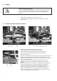
2. Einbau Vorsicht Verletzungsgefahr! Schalten Sie den Hauptschalter aus und ziehen Sie den Netzstecker, bevor sie mit dem Einbau der pneumatischen Fußlüftung beginnen. Der Einbau darf nur von qualifizierten Technikern durchgeführt werden. – – Kippen Sie die Nähmaschine nach hinten ab. Lösen Sie die 6 Schrauben der Ölwanne und nehmen Sie die Ölwanne ab. 2.
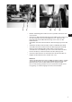
6 9 10 11 12 – Mit der Verbindung WI-N 12 müssen Sie jetzt den Schlauch nach unten führen. – Stecken Sie dazu die Befestigungsschelle 10 auf den Schlauch 6. Um die Länge des Schlauches 6 abzumessen, halten Sie die Befestigungsschelle 10 an die Bohrung rechts unten an der Nähmaschine. Schneiden Sie den Schlauch 6 hinter der Befestigungsschelle 10 ab. – Verbinden Sie die Schlauchenden mit der Verbindung WI-N 12.
2.2 Gestänge durch neues Gestänge ersetzen 1 6 2 3 4 5 6 7 – Schrauben Sie in die obere Bohrung den Schalldämpfer 7 ein. Schrauben Sie in die beiden anderen Bohrungen die Verschraubungen GD-E 5 und 6 ein. Ziehen Sie die Verschraubungen 5 und 6 an, damit die Gewinde mit der aufgetragenen Dichtungsmasse richtig abdichtet werden. – Entfernen Sie die Muttern des alten Gestänges an dem Pedal 1 und an dem Antrieb 4. Entfernen Sie das alte Gestänge.
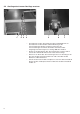
2.3 Wartungseinheit anbringen und anschließen 8 5 6 12 13 9 D 9 – Schrauben Sie die Schlauchtülle 10 in den würfelförmigen Anschluss 12 der Wartungseinheit 13. – Entfernen Sie das Verbindungsstück 8 mit den Dichtungsscheiben aus der Wartungseinheit 13 und ersetzen Sie es durch die Verschraubung WI-E 9. – Schrauben Sie die Wartungseinheit 13 so an das Untergestell, dass der Wasserabscheider möglichst senkrecht nach unten zeigt.
Für Ihre Notizen: 8
Foreword This instruction manual is intended to help the user to become familiar with the machine and take advantage of its application possibilities in accordance with the recommendations. The instruction manual contains important information on how to operate the machine securely, properly and economically. Observation of the instructions eliminates danger, reduces costs for repair and down-times, and increases the reliability and life of the machine.
General safety instructions The non-observance of the following safety instructions can cause bodily injuries or damages to the machine. 1. The machine must only be commissioned in full knowledge of the instruction book and operated by persons with appropriate training. 2. Before putting into service also read the safety rules and instructions of the motor supplier. 3. The machine must be used only for the purpose intended. Use of the machine without the safety devices is not permitted.
Index Page: Preface and general safety hints Fitting the pneumatic foot lift class 367 (Edition 04/2010) 1. General information 1.1 Scope of delivery . . . . . . . . . . . . . . . . . . . . . . . . . . . . . . . . . . . . . . . . . . . . . . . 3 2. 2.1 2.2 2.3 Fitting Replace the slide bar by a cylinder . . . . . . . . . . . . . . . . . . . . . . . . . . . . . . . . . . . . Replace bars by new bars . . . . . . . . . . . . . . . . . . . . . . . . . . . . . . . . . . . . . . . . . .
1. General information The subclass 367-170010 can be retrofitted with the pneumatic foot lift. ATTENTION! The operating pressure of class 367 amounts to 6 bar. Should the pressure of your supply line be higher than 6 bar, it has to be reduced to 6 bar at the supply unit of the sewing machine! 1.1 Scope of delivery Before you start the installation: Please check whether all components of the retrofit kit are included in the scope of delivery.
2. Fitting Caution: Danger of injury! Switch off the main switch and pull out the mains plug before you start to install the pneumatic foot lift. The installation must be done by qualified technicians only. – – Tilt the sewing machine to the back. Loosen the 6 screws of the oil pan and take the oil pan off. 2.1 Replace the slide bar by a cylinder 1 7 4 2 1 3 4 5 3 6 – Remove the locking washer 3from the right end of the slide bar 2 and the screw 1 from the left end of the slide bar 2.
6 9 10 11 12 – Now you have to guide the hose downward with the connection WI-N 12. – For this purpose put the fastening clip 10 on the hose 6. In order to measure the length of the hose 6, hold the fastening clip 10 close to the drill-hole down on the right of the sewing machine. Cut the hose 6 off behind the fastening clip 10. – Connect the hose ends with the connection WI-N 12.
2.2 Replace bars by new bars 1 6 2 3 4 5 6 7 – Screw the sound absorber 7 in the upper drill-hole. Screw the screw connections GD-E 5 and 6 in the other two drill-holes. Tighten the screw connections 5 and 6 so that the threads are correctly sealed by the applied sealing compound. – Remove the nuts of the old bars at pedal 1 and drive 4. Remove the old bars. – Fit the new bars 3 instead of the old bars. Put on the washers and screw on the nuts 1 and 4 again.
2.3 Fit and connect the maintenance unit 8 5 9 Screw the hose nozzle 10 in the cubical-shaped connection 12 of the maintenance unit 13. – Remove the connecting piece 8 with the washers from the maintenance unit 13 and replace it by the screw connection WI-E 9. – Screw the maintenance unit 13 on the stand in such a way that the water separator shows downward in a vertical direction. If you have got the stand MG 55-3, fit the maintenance unit 13 at the cross bar on the right beneath the drive.
Your own notes: 8