LP 2971 LP 2974 Industrial sewing machine Instruction manual Postfach 17 03 51, D-33703 Bielefeld • Potsdamer Straße 190, D-33719 Bielefeld Telefon +49 (0) 521 / 9 25-00 • Telefax +49 (0) 521 / 9 25 24 35 • www.duerkopp-adler.com Ausgabe / Edition: 06/2012 Änderungsindex Rev. index: 00.0 Printed in Czech Republic Teile-Nr./Part.-No.
All rights reserved. Property of Dürkopp Adler AG and copyrighted. Reproduction or publication of the content in any manner, even in extracts, without prior written permission of Dürkopp Adler AG, is prohibited.
Foreword This instruction manual is intended to help the user to become familiar with the machine and take advantage of its application possibilities in accordance with the recommendations. The instruction manual contains important information on how to operate the machine securely, properly and economically. Observation of the instructions eliminates danger, reduces costs for repair and down-times, and increases the reliability and life of the machine.
General safety instructions The non-observance of the following safety instructions can cause bodily injuries or damages to the machine. 1. The machine must only be commissioned in full knowledge of the instruction book and operated by persons with appropriate training. 2. Before putting into service also read the safety rules and instructions of the motor supplier. 3. The machine must be used only for the purpose intended. Use of the machine without the safety devices is not permitted.
Contents Page: Introduction and safety instructions Part 1: Operating Instructions LP 2971, LP 2974 – Original Instructions (Edition 06/2012) 1 Product description . . . . . . . . . . . . . . . . . . . . . . . . . . . . . . . . . . . . . . . . . . . 5 2 Designated use . . . . . . . . . . . . . . . . . . . . . . . . . . . . . . . . . . . . . . . . . . . . . . 5 3 Subclasses . . . . . . . . . . . . . . . . . . . . . . . . . . . . . . . . . . . . . . . . . . . . . . . . .
Notes:
1 Product description The Dürkopp Adler LP 2971, LP 2974 is a special sewing machine for universal use. 2 • • It is a double lockstitch post bed sewing machine . • The machine is either single needle or double needle unit with automatic functions such as thread trimming, automatic backtacking, automatic foot lifting, or without them. • • • • The machine is equipped with a large two part vertical hook.
3 6 Subclasses LP 2971 Single-needle double lockstitch post bed sewing machine with feed wheel, needle feed with driven roller foot and large hook, electro-magnetic thread cutter, electro-magnetic seam bartacking and sewing foot lifting. LP 2974 Double-needle double lockstitch post bed sewing machine with feed wheel, blocked needle feed with driven roller foot and large hook, electro-magnetic thread cutter, electro-magnetic seam bartacking and sewing foot lifting.
4 Optional equipment The following optional equipments are available for the class LP 2971, LP 2974 : Optional equipment Subclasses 9880 888101 Integrated sewing light with 2 LED, incl.
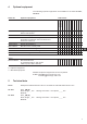
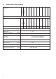
5.1 Technical data of the subclasses LP 2974 LP 2971 Subclasses Type of stitch Lock stitch 301 Needle system Needle size (depending on E-No.) Max. thread thickness 8 large Number of needles large Hook type 1 2 134 160 [Nm] [Nm] 10/3 Stitch length Forwards Backwards [mm] Max. Speed [min ] 3000 Number of stitches with factory setting [min ] 2500 Max. sewing foot stroke [mm] 12 Dimensions (H x W x D) [mm] 7 (5 for E55/2.0 and E56/2.4) 7 (5 for E55/2.0 and E56/2.
6 Operation 6.1 Threading the needle thread B A 2 1 GB 1 C 2 3 D 2 1 Caution! Risk of injury! Turn off the main switch. The needle thread may only be threaded with the sewing machine switched off. – – – – Thread the single needle machine according to fig. (A). Thread the double needle machine according to fig. (B). The thread (1) designed for the left needle is to be threaded in the left tensioners and in the upper hole in the thread lever (3).
6.2 Winding the hook thread 1 2 – – – – – – 6.3 3 4 Thread the thread according to the picture. Insert the thread under the knife (1) and tear off by pulling in the arrow direction (2). Fix the bobbin and press the lever (3) in the direction (4). Start the machine up. After the thread winding, slide the thread under the knife again (1) and tear it off. Insert another bobbin immediately and press the lever (3).
6.4 Adjusting the thread tension 6.4.1 Adjusting the hook thread tension 1 3 2 Caution! Risk of injury! Turn off the main switch. The hook thread tension may only be adjusted with the machine switched off. – – – Adjust the hook thread tension via the screw (1). Insert a screwdriver through the hole (2). Increase the tension by tightening the screw. Measure the thread tension with a dynamometer. Thread the thread according to the picture and pull in the arrow direction (3).
6.4.2 Adjusting the needle thread tension 1 2 3 Adjusting the pre-tensioner (1) – When the main tensioner (3) and supplementary tensioner (2) are open, the needle thread must be under slight residual tension. This residual tension is produced by the pre-tensioner (1). The pre-tensioner (1) simultaneously affects the length of the end of the severed needle thread, the starting thread for the next seam. (Tensioner (1) is not switched off at the foot lifting).
6.5 Switching on/off the thread tensioners 1 2 3 – Tensioner (1) is never switched off. – Tensioners (2) and (3) are switched off with an electric magnet at the foot automatic lifting. If the automatic foot lifting at the machine stop is pre-selected, the tensioners are switched off, but temporarily only, so that the switching off electric magnet does not overheat. Tensioners (2) and (3) are also switched off temporarily during the trimming cycle.
6.6 Adjusting the thread regulator 2 1 The thread regulator (2) controls the quantity of needle thread required for stitch formation. The thread regulator must be precisely adjusted for an optimum result. – Loosen the screw (1), shift the thread regulator (2), and tighten the screw (1).
6.7 Changing the needle with single-needle machines with the hook on the right 1 2 3 MAX. 3° 4 5 6 Caution! Risk of injury! Replace the needle with the main switch switched off and the motor stopped. – – – – GB Turn the hand wheel, until the needle bar (1) has reached its highest position. Loosen screw (2). Remove the needle and insert a new one with the needle scarf (3) to the right [see section (4) or (5)]. The needle may not be oriented as shown at section (6). Tighten screw (2).
6.8 Changing the needle with double-needle machines 1 2 3° MAX. 3 4 5 Caution! Risk of injury! Turn off the main switch. The needles may only be changed with the sewing machine switched off. – – – Loosen the screws (1). Remove the needle and insert new ones with the needle scarf (2) oriented as shown above [see section (3) or (4)]. The needles may not be oriented as shown at section (5). Tighten the screws (1). Caution! Danger of breakage! A false orientation of the needle may damage the hook point.
6.9 Lifting and folding the roller presser 1 2 Lifting the roller presser with a hand lever – Lift the roller presser by the lever turning (1) in the arrow direction to the stop (the roller presser remains lifted, the lever (1) remains tilted). – Lower the roller presser by putting the lever (1) to the initial position. – After the roller presser lifting with the hand lever, the machine may be started up (e.g. for hook thread winding).
Roller presser folding Caution! Risk of injury! Roller presser folding to be done at main switch off and standing motor. – – Lift the roller presser with the hand lever. Lift the roller presser by pressing in the signed direction. 6.10 Sewing-foot pressure through the setting wheel + 1 – – – – 18 The required sewing-foot (roller) pressure is set with the setting wheel (1). To increase the roller pressure = turn the setting wheel (1) clockwise.
6.11 Sewing backward (backtacking) 1 Backtacking with the lever – Push the stitch regulator lever (1) downwards. The machine sews backward stitches as long as the stitch regulator lever (1) is being pushed. Automatic backtacking (bartacking) – In the machines equipped with the positioning motor it is possible to pre-select the backtacking by a pre-selected backstitches number both at the beginning and at the seam end.
6.13 Switching on the safety clutch at the hook blocking 2 1 – If the thread gets in the hook way, the hook gets blocked and it is subsequently disconnected from the motor by the safety clutch. Caution! Risk of injury! Turn off the main switch. Switch the safety clutch on, with the sewing machine switched off. – – – – 20 Turn the hand wheel until you hear a switching click (snapping) of the safety clutch. Turn the hand wheel in the opposite direction until the hook gets released.
6.14 Controlling the machine equipped with a positioning motor 6.14.1 Using the pedal -2 -1 0 1 2 13 The pedal position is scanned by a sensor distinguishing 16 levels. The meaning is given in the table: Pedal position Pedal motion Meaning -2 Over heel fully backwards -1 Over heel slightly backwards 0 Neutral position See notes 1 Slightly forwards Command for foot lowering 2 Further forwards Sewing at minimum speed (1. speed gear) 3 Further forwards Sewing - 2.
6.14.2 Using the key 1 Key 22 2 Function 1 Manual sewing backward The machine sews backward stitches as long as the key is being pushed.
7 Positioning drive Efka DC1550/DA321G GB DA321G control contains all necessary operating elements to switch the functions over and to set the parameters. The operation is possible without the control panel, it is not possible only to program the sewing. It is possible to connect the control panel V810 and V820, which are available as an attachment. It is possible to program the sewing by the control panel V820.
8 Sewing with machine with positioning motor 8.
Automatic function codes are described in the attached drive manufacturer´ s Instruction Leaflet. The drive manufacturer’s Instruction Leaflet for Efka DA321G drive is available on website www.efka.net. Some automatic functions can be preset by means of push buttons. Their description is included in the booklet “Efka Operation Instructions”. Other automatic functions can be preset through the drive parameter change. Every function like this has its parameter number.
9. Maintenance 9.1 Cleaning and checking Caution! Risk of injury! Turn off the main switch. Maintenance may only be carried out with the machine switched off! Maintenance work must be carried out no less frequently than at the intervals given in the tables (see ”operating hours” column). Maintenance intervals may need to be shorter when processing heavy-shedding materials. A clean machine is a trouble-free machine.
2 1 Maintenance work to be carried out Explanation Operating hours - Clean the oil sump Clean the oil sump (1) of dirt and contaminated oil. (you may use a special vacuum cleaner.) Remove lint and pieces of thread from air-intake openings (2) (e.g. with an air blow gun).
9.2 Lubrication 2 1 3 Caution! Risk of injury! Oil can cause skin eruptions. Avoid protracted contact with the skin. In the event of contact, thoroughly wash the affected area. Caution! The handling and disposal of mineral oils is subject to legal regulation. Deliver used oil to an authorised collection point. Protect your environment. Take care not to spill oil.
Contents Page: Part 2: Installation Instructions LP 2971, LP 2974 – Original Instructions 1 Scope of delivery . . . . . . . . . . . . . . . . . . . . . . . . . . . . . . . . . . . . . . . . . . . . . 3 2 Transport packing of assembled machine . . . . . . . . . . . . . . . . . . . . . . . . . . . . . 4 3 3.1 3.2 3.3 Assembling the stand Assembling the stand components . . . . . . . . . . . . . . . . . . . . . . . . . . . . . . . . . . . Assembling the table top (direct drive) . . . . . . . . . . .
Notes:
1 Scope of delivery The purchaser can order a complete machine, or some components only. Prior to setting up, please check that all the required parts are present. This description refers to a special sewing machine, of which all individual components can completely be delivered by Dürkopp Adler AG.
2 Transport packing of assembled machine If the machine is supplied in assembled condition, the following transport packing must be removed: – Safety straps and wooden battens on the machine head and stand. – Safety blocks and straps on the sewing drive. 3 Assembling the stand 3.1 Assembling the stand components 3 1 2 – – 4 Mount the frame according to the picture. Mount the pedal (1) provisionally. Its position will be adjusted after the whole machine is complete.
3.2 Assembling the table top (direct drive) 10 8 9 2 3 5 6 1 10 7 260 4 11 15 36 8 14 50 460 80 15 15 180 12 13 15 32 8 80 30 30 72 770 GB 185 – – – – – – – – – – – – – – – Turn the table top (1) upside down. Screw the electric cable channel (2). Screw the pedal position sensor (3). Screw the electric cable clip (4). Put the oil sump on (5) and slide it in the arrow direction (6) till the relevant protrusions of the oil sump are seated on the recess contour.
3.3 Setting the working height 1 – – – – The stand height is adjustable between 750 and 900 mm. Loosen the screws (1). Set the required table top height and make sure that it is identical on both sides. To do that, use the scale on the stand feet. Set the stand height so that it corresponds with the operator’s body proportions. Tighten both screws (1). Caution! Risk of injury! Failure to adjust the stand height to the operator’s body proportions can cause damage to the operator’s locomotion system.
4 Assembling the machine head 4.1 Fitting the machine head 1 2 GB – – Tilt the machine head (1) and insert it in the table top recess. After the head insertion, screw the locking plate (2) immediately to secure the machine head against falling out at its tilting. The locking plate is part of the machine head accessories.
4.2 Fitting the belt guards 1 3 2 – – – – 8 Disassembly the hand wheel (1). In the machines with the motor on the sewing head and with 1,55:1 toothed belt driving gear, mount the proximity switch (3). It is included in the “kit for motor“. In all machines with the motor on the machine head mount the guard (2) (it is included in of the motor part set). Mount the hand wheel (1).
4.3 Adjustment of pedal position 2 90° 2 1 3 GB – – Adjust the side position of the pedal (1) so that its center lies on the needle axis. Adjust the draw rod (2) so that the foot axis is perpendicular to the pedal surface. Caution! Risk of injury! Failure to keep the determined pedal position can cause damage to the operator’s locomotion system.
4.4 Fitting the oil pump pipe 1 2 4 3 – – – 10 Tilt the machine head (1). Attach the pipe (2) with the clips (3) and install the suction basket (4). TIlt the machine head.
4.5 Fitting the connecting cable, control panel and sewing diode lamp on the machine head 1 2 4 3 6 5 9 GB 7 8 – – – – – – – The connecting cable (1) is supplied with every machine with the positioning motor (drive). The control panel (2) had to be ordered separately (optional equipment). When ordering a control panel, a bracket (3) is always supplied together with it. The sewing lamp LED (5) is an optional equipment.
5 Electrical connection The machine drive is supplied from the low voltage network. Caution! All work on the electrical equipment of this special sewing machine may only be carried out by qualified electricians or other appropriately trained persons. Remove the mains plug before carrying out any work! 5.1 Electrical connection to low voltage network According to the selected type the machine drive has a one-phase or three-phase supply.
5.1.1 Sewing lamp transformer connection to network voltage Caution! Risk of electric current injury! The sewing lamp transformer is not switched off by the main switch (EN 60 204-31)! At the sewing lamp installation and repair inside the transformer box, e.g. at a fuse replacement, the mains plug must be disconnected from the power outlet. The machine is equipped with the Efka DC1550/DA321G drive GB 2 6 5 1 – – – – – – – – – – – – 6 5 4 3 Pull the mains plug from the power outlet.
5.2 Grounding 1 2 – – – – The grounding conductor (1) is included in the accessory package of the machine head. Connect the conductor (1) to the plug (2) and pull its opposite end under the table top. Screw the opposite end of the grounding conductor to the relevant grounding point of the drive (indicated ). Attach the conductor with a clip on the bottom side of the table top. Caution! Make sure that the grounding conductor does not touch the driving V-belt (if there is any).
5.3 Connection of the head to Efka DC1550/DA321G drive Efka DC1550/DA321G direct drive is fixed directly on the machine head. The motor synchronizer is incorporated in the motor body and it is not located on the hand wheel (this applies, however, only for the 1:1 gear reduction motor – machine). B 4 1 M B 2 B 8 0 M E B ... B 1 8 L S M ... B 7 7 6 V 8 . . A GB 74 1 2 – – – – – – 9 3 5 6 8 Connect the machine head connecting cable to the connector (1).
6 Adjustment of Efka positioning motor (drive) The function of the positioning motor (drive) is defined by its program, drive parameter setting, and the machine stopping positions. If the machine is supplied in the disassembled condition, the drive setting must be carried out by the purchaser. If the sewing machine is supplied in assembled condition, the drive is already set by the sewing machine manufacturer. 6.
6.1.3 Values of parameters specific for LP 2971, LP 2974 Parameter change for machines with gear rate of 28/28 teeth Parameter Original value New value Parameter description 290* 0 3 Class of the machine 111 - - Max. sewing speed 170 - - Reference position (see chapter 6.2.2) Parameter change for machines with gear rate 18/28 teeth Parameter Original value New value Parameter description 290* 0 4 Class of the machine 111 - - Max.
6.2.3 Checking of set positions Position 1 – Switch on the network switch. – Tread the pedal forwards shortly and release. The machine is stopped in the position 1 (see chapter 6.2.1). – Check the angle on the hand wheel scale (225° ± 5°). Position 2 – Tread the pedal forwards shortly at first and then entirely backwards with the heel until the machine stops. The machine stops in the position 2 (see chapter 6.2.1). – Check the angle on the hand wheel scale (35° ± 5°). 6.
7 Lubrication Before start, the machine must be lubricated properly with oil according to chapter 9.2 in the operating instructions. 8 Sewing test This test can be carried out only after the machine is set completely. – Thread in the bobbin-winder thread. (see operating instructions). – Turn on the main switch. – Lock the sewing foot in the lifted position (see operating instructions). – Fill the bobbin at low speed. – Turn off the main switch .