512/532 Operating Instructions
All rights reserved. Property of Dürkopp Adler AG and protected by copyright. Any reuse of these contents, including extracts, is prohibited without the prior written approval of Dürkopp Adler AG.
Contents 1 About this operating manual.............................................................. 5 1.1 1.2 1.3 1.4 1.5 1.5.1 1.5.2 Scope .................................................................................................... 5 For whom is this operating manual? ..................................................... 5 Representation conventions – symbols and characters ........................ 6 Other documents ...............................................................................
Contents 5.8 5.9 5.10 5.11 5.12 5.13 5.14 5.14.1 5.14.2 5.14.3 5.15 5.16 5.17 5.18 5.19 5.19.1 5.19.2 5.20 5.21 5.22 5.23 5.24 5.24.1 5.24.2 5.24.3 5.24.4 Changing the seam appearance ......................................................... 40 Bobbin winding .................................................................................... 40 Sewing................................................................................................. 41 Counter.................................................
Contents 8.3.7 8.3.8 8.3.9 8.3.10 8.3.11 8.3.12 8.4 8.5 Fitting the oil collection reservoir ......................................................... 77 Electrical connection ........................................................................... 78 Checking the mains voltage ................................................................ 78 Connecting the cables to the controller ............................................... 78 Mount the hood .......................................................
Contents 4 Operating Manual 512/532 Version 00.
About this operating manual 1 About this operating manual This operating manual for the special sewing machines 512 and 532 was compiled with the utmost care. It contains information and notes in order to make long-term and reliable operation possible. Should you notice any discrepancies or if you have improvement requests, then we would be glad to receive your feedback, 4.11 Customer service. Consider this operating manual part of the product and keep it on hand at all times.
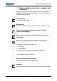
About this operating manual 1.3 Representation conventions – symbols and characters Various information in this operating manual is represented or highlighted by the following characters in order to facilitate easy and quick understanding: Correct setting Indicates proper setting. Malfunctions Specifies the faults that can occur due to an incorrect setting.
About this operating manual Information Additional information, e. g. on alternative operating possibilities. Order Specifies the work to be performed before or after a setting. References Reference to another section in the manual. Safety Important warnings for the machine operator are specially designated. Since safety is of particular importance, hazard symbols, levels of danger and their signal words are described separately in 3 Safety Information.
About this operating manual 1.5 Liability All information in this operating manual was compiled with consideration to the state of the art, and applicable standards and regulations. The manufacturer cannot be held liable for damages resulting from: • Breakage and transport damages • Failure to observe operating manual • Improper use • Unauthorized modifications to the machine • Use of untrained personnel • Use of unapproved replacement parts 1.5.
About this operating manual The machine may only be set up and operated in dry conditions on well-maintained premises. If the machine is operated on premises that are not dry and well-maintained, then further measures may be required which must be compatible with EN 60204-31:1999. Only authorized/trained personnel may operate the machine. The manufacturer cannot be held liable for damages resulting from improper use. WARNING Risk of electric shock, crushing and punctures! Improper use can result in injury.
About this operating manual 10 Operating Manual 512/532 Version 00.
Technical Specifications 2 Technical Specifications The Dürkopp Adler 512 is a CNC double lockstitch bartack sewing machine. Die Dürkopp Adler 532 is a button sewing machine. 2.1 Characteristics of the 512 The existing programs are scalable and can be saved in this modified form. The machine is equipped with an automatic sewing foot lifter, thread cutter, thread wiper, a needle thread clamp below the stitch plate for reliable sewing-on and an integrated DC direct drive including an operating panel.
Technical Specifications 2.2 Characteristics of the 532 The existing programs are scalable and can be saved in this modified form. The machine is equipped with an automatic sewing foot lifter, thread cutter, thread wiper, a needle thread clamp below the stitch plate for reliable sewing-on and an integrated DC direct drive including an operating panel. Technical features • The sewing machine is driven by an integrated positioning drive.
Technical Specifications 2.3 Declaration of conformity The machine complies with the European regulations specified in the declaration of conformity or in the installation declaration. 2.4 Technical data Class 512 532 Stitch type 301 301 Hook type Oscillating hook Oscillating hook 1 1 134 | DPx5 135x17 | DPx17 80 - 130 | 12 - 20 80 - 110 | 12 - 18 Depends on seam appearance (0.1 - 10 mm) Depends on seam appearance (0.
Technical Specifications Class 512 532 Operating pressure [bar] -- -- Air consumption [NL] -- -- Length, width, height [mm] (upper section incl. packaging) 870 /430 / 890 870 /430 / 890 Length, width, height (upper section only) [mm] 660 / 230 / 430 660 / 230 / 430 Weight (upper section, excluding controller) [kg] 69 69 Length, width, height (controller incl.
Safety Information 3 Safety Information This section contains basic information for your safety. Read the instructions carefully before setting up or operating the machine. Make sure to follow the information included in this section. Failure to do so can result in serious injury and damage to the machine. 3.1 Basic safety instructions The machine may only be used as described in this operating manual. The operating manual should be available at the machine's location at all times.
Safety Information Obligations Observe the country specific safety and accident prevention of the operator regulations and the legal regulations concerning industrial safety and the protection of the environment. All warnings and safety signs on the machine must always be in legible condition and may not be removed. Missing or damaged labels should be replaced immediately. Requirements to The machine should only be set up by qualified technicians.
Safety Information 3.2 Signal words and symbols used in warnings Warnings in the text are distinguished by color bars. The color scheme is oriented towards the severity of the danger. Signal words indicate the degree of risk: Signal words Signal words and the endangerment that they describe: Signal word Endangerment DANGER Will result in serious injury or death. WARNING Can result in serious injury or death. CAUTION Can result in minor or moderate injury. ATTENTION Can result in property damage.
Safety Information DANGER Type and source of risk Consequences of non-observance Measures for avoiding the risk This is what a warning looks like for a hazard that will result in serious injury or even death if not complied with. WARNING Type and source of risk Consequences of non-observance Measures for avoiding the risk This is what a warning looks like for a hazard that could result in serious injury or even death if not complied with.
Safety Information CAUTION Type and source of risk Consequences of non-observance Measures for avoiding the risk This is a warning note for a hazard that could result in environmental damage if not complied with. Operating Manual 512/532 Version 00.
Safety Information 20 Operating Manual 512/532 Version 00.
Operation 4 Operation 4.1 Threading needle thread CAUTION Risk of injury from needle and moving parts Only thread the needle thread with the sewing machine switched off. 1. Plug the thread reels onto the thread reel holders and feed the needle and hook threads through the unwinding bracket. The unwinding bracket must stand horizontally above the thread reels. 2. Thread the needle thread as shown in the following figure.
Operation 4.2 Setting the needle thread tension Figure 2: Setting the needle thread tension ① ② (1) – Preliminary tensioner knurled nut (2) – Primary tensioner Preliminary tension of the needle thread With an open primary tensioner (2) a small amount of residual tension of the needle thread is required. The residual tension is generated by the preliminary tensioner (1). The preliminary tension also affects the length of the cut needle thread end (starting thread for the next seam). 1.
Operation Opening the needle thread tensioner The primary tensioner (2) is automatically opened during thread cutting and when the clamping foot is raised. 4.3 Setting the thread regulator CAUTION Risk of injury from needle and moving parts Only thread the needle thread with the sewing machine switched off. Figure 3: Setting the thread regulator ③ ① ② (1) – Thread regulator (2) – Thread tensioning spring Operating Manual 512/532 Version 00.
Operation The thread regulator (1) regulates the amount of needle thread required for forming the stitch. An optimum sewing result is only possible when the thread regulator is exactly adjusted. With the correct setting the needle thread loop must slide over the thickest part of the hook at low tension. 1. Loosen the screw (3). 2. Adjust the position of the thread regulator (1). Thread regulator to the left = larger amount of needle thread Thread regulator to the right = smaller amount of needle thread 3.
Operation 1. Fit the bobbin (2) on the bobbin shaft (3). 2. Pull the thread through the guide (5) and around the tensioner (6). 3. Wind the thread counterclockwise approx. 5 x around the bobbin core (2). 4. Press the bobbin lever (4) into the bobbin. 5. Start sewing. The bobbin winder stops automatically when the configured bobbin filling length has been reached (see Service manual). 6. Tear off the thread at the thread clamp (1) after winding.
Operation Figure 5: Replacing the hook thread bobbin ① ⑤ ④ ② ③ (1) – Bobbin housing flap (2) – Bobbin housing upper section (3) – Hook cover ⑥ ② ⑦ (4) – Hole (5) – Tension spring (6) – Bobbin (7) – Bobbin housing slot Remove the empty bobbin 1. Pull the hook cover (3) downwards. 2. Lift the bobbin housing flap (1). 3. Remove the bobbin housing upper section (2) with the bobbin (6). 4. Remove the empty bobbin from the bobbin housing upper section (2). Insert a full bobbin 1.
Operation 4.6 Setting the hook thread tension CAUTION Risk of injury from needle and moving parts Only thread the hook thread tensioner with the sewing machine switched off. Figure 6: Setting the hook thread tension ① ② ③ (1) – Tension spring (2) – Regulating screw (3) – Bobbin housing upper sectio The required hook thread tension must be generated by the tensioning spring (1). The bobbin housing upper section (3) should slowly fall under its own weight when held by the threaded hook thread.
Operation 4.7 Changing needle CAUTION Risk of injury from needle and moving parts Only change the needle with the sewing machine switched off. Figure 7: Changing needle ③ ① ② (1) – Groove (2) – Screw (3) – Needle bar 1. Loosen the screw (2) and remove the needle. 2. Insert the new needle into the hole in the needle bar (3) as far as it will go, taking care to ensure that the groove in the needle (1) faces the hook tip. 3. Tighten the screw (2). 4.
Operation 4.8 Adjusting the button mount of the button clamp (Class 532) CAUTION Risk of injury from needle and moving parts Only change needles with the sewing machine switched off. Figure 8: Adjusting the button mount – standard clamp ① ④ ② ③ (1) – Button mount, left (2) – Lever Operating Manual 512/532 Version 00.
Operation Figure 9: Adjusting the button mount – optional clamp ④ ① ③ ② (1) – Button mount, left (2) – Lever (3) – Knurled screw (4) – Button mount, left The button should be able to slide lightly into the button mount and be easy to align. However, the button must be securely clamped so that it cannot twist when the sewing material is inserted. The lever (2) regulates the size of the opening in the button mount. 1. Switch on the sewing machine. 2. Press the Ready button.
Operation 7. Tighten the knurled screw (3). 8. Remove the button. 9. Adjust the button mount so that the button is securely held, by loosening the knurled nut (3) and lightly adjusting the lever (2). 4.9 Shank shaper (optional) Figure 10: Shank shaper ④ ③ ② ① (1) – Adjustment screw (2) – Pivot lever (3) – Shank shaper (4) – Screw The button clamp can be optionally equipped with a shank shaper (3). Pivoting the shank shaper in/out 1.
Operation Adjusting the position of the shank shaper The position of the shank shaper (3) can be adjusted to suit different button diameters. 1. Loosen the screw (4). 2. Adjust the shank shaper in the Y direction. 3. Tighten the screw (4). 4.10 Sewing Operating and function sequence when sewing: Sewing process Operation / Explanation Starting situation before sewing Pedal in the rest position. Sewing machine is at a standstill. Needle raised, clamp raised. The Ready button LED illuminates.
Operation 4.11 Customer service Contact for repairs if machine is damaged: Dürkopp Adler AG Potsdamer Str. 190 33719 Bielefeld Tel. +49 (0) 180 5 383 756 Fax +49 (0) 521 925 2594 Email: service@duerkopp-adler.com Internet: www.duerkopp-adler.com Operating Manual 512/532 Version 00.
Operation 34 Operating Manual 512/532 Version 00.
Settings via the software 5 Settings via the software 5.1 Control panel Figure 11: Control panel ⑤ ⑥ ⑦ ⑧ ⑨ ⑩ ⑪ ④ ③ ② ⑫ ① Control panel buttons: Button / LED Pos. Function (1) USB button with LED Save/load seam appearances to/from a USB stick. (2) Needle thread clamp button with LED Clamps the needle thread on the first stitch. LED on = Needle thread clamp on LED off = Needle thread clamp off (3) Memory button Perform memory functions. Operating Manual 512/532 Version 00.
Settings via the software Button / LED Pos. Function (4) Reset button Delete an error and restore settings. (5) Ready button with LED Switch between programming and sewing mode. LED on = sewing mode LED off = programming mode (6) Error LED LED on = error (7) Program display Display parameters. (8) +/– Program buttons Change parameters and navigate forwards / backwards. (9) Function display Display values for selected functions / programs.
Settings via the software 5.3 Referencing the machine 1. Press the Ready button. The button LED illuminates. 2. Press the Ready button. The button LED goes out. 5.4 Selecting the seam appearance ATTENTION Damage to the needle if the size of the seam appearance does not match the clamping foot. Check the clamping foot and adjust if necessary. Prerequisite: • Machine is in programming mode, Ready button LED is off. 1.
Settings via the software 5.5.2 Scaling the Y axis 1. Press the Select button until the Y axis symbol LED illuminates. 2. Press the +/– Function buttons until the desired Y axis value is reached. 100 % corresponds to the specified dimensions of the selected seam appearance. 5.5.3 Recalculate the button hole clearance (class 532) The button hole clearance is preset to 3.4 mm (3.4 mm = 100 %). The button hole clearance can be set by changing the percentage value.
Settings via the software 5.5.4 Recalculate the bartack dimensions (class 512) The following formula is used for converting the preset dimensions to the desired dimensions: Value to be set = (100 % : preset dimension) * desired value Example Preset dimension in the X direction = 16 mm Desired value in the X direction = 10 mm Value to be set = (100 % : 16 mm) * 10 mm = 62.5 % 5.6 Setting the speed Important Changes to the speed only take effect temporarily.
Settings via the software 5.8 Changing the seam appearance 1. Press the Select button until the Pattern Number symbol LED illuminates. 2. Press the +/– Function buttons until the desired seam appearance number is shown in the Function display. 3. Press the Ready button. 5.9 Bobbin winding Prerequisite: • Needle removed. • Needle thread not threaded. 1. Press the Ready button. The button LED illuminates. 2. Press the Ready button. The button LED goes out. 3.
Settings via the software 5.10 Sewing Prerequisite: • Machine is in sewing mode, Ready button LED illuminates. • Needle is fitted. • Needle thread is threaded. • Seam appearance is selected. 1. Insert the material to be sewn. 2. Press the foot pedal forwards to the first position. The clamp lowers. The clamp raises when the pedal is released. 3. Briefly press the foot pedal fully forwards. Sewing process starts. The clamp raises automatically at the end of sewing. 5.
Settings via the software 5.12 Pausing sewing 1. Press the Reset button or press the pedal backwards. Sewing process paused, display shows error message E-50. 2. Press the Reset button or press the pedal forwards to continue sewing. 5.13 Disabling standard seam appearances Standard seam appearances can be disabled so that they are no longer displayed. Prerequisite: • Machine is in programming mode, Ready button LED is off. 1. Press the Memory button and button P1 at the same time.
Settings via the software Sewing appearance memory button combinations Memory number Button combination Memory number Button combination Memory number Button Memory combination number Button combination P1 P1 P8 P1 + P4 P15 P4 + P5 P22 P2 + P3 + P4 P2 P2 P9 P1 + P5 P16 P1 + P2 + P3 P23 P2 + P3 + P5 P3 P3 P10 P2 + P3 P17 P1 + P2 + P4 P24 P2 + P4 + P5 P4 P4 P11 P2 + P4 P18 P1 + P2 + P5 P25 P3 + P4 + P5 P5 P5 P12 P2 + P5 P19 P1 + P3 + P4 P6 P1 + P2 P13 P3 + P4 P
Settings via the software 9. Press the Memory button to exit the memory mode. 10. Check the seam appearance ( 5.7 Checking the seam appearance, p. 39). 5.14.2 Sewing with the memory buttons 1. Press the desired seam appearance memory button (or button combination). 2. Press the Ready button. 3. Check the seam appearance form. 4. Sew with the selected seam appearance. 5.14.3 Deleting the memory button assignments Prerequisite: • Machine is in programming mode, Ready button LED is off. 1.
Settings via the software appearance. 6. Press the +/– Function buttons to sew the 3rd seam appearance. 7. Press the +/– Function buttons to sew the 4th seam appearance. 8. Press the Ready button to confirm the seam appearance sequence. The Program shows the memory location, the Function display shows the number of seam appearances. 9. Press the Memory button to exit the memory mode. 5.16 Sewing with a seam appearance sequence Prerequisite: • Machine is in programming mode, Ready button LED is off. 1.
Settings via the software sequence (C01 ~ C25). 3. Press the Ready button to confirm the seam appearance sequence. 4. Press the Reset button to delete the seam appearance sequence. 5. Press the Ready button to confirm the deletion. 6. Press the Memory button to exit the memory mode. 5.18 Finishing sewing CAUTION Risk of injury from needle and moving parts Do not reach under the raised clamp. 1. Press the Ready button. The button LED illuminates. The controller is in the sewing mode. 2.
Settings via the software Function display shows the parameter value. 2. Press the +/– Program buttons to select a different parameter. 3. Press the Ready button to confirm the parameter. The button LED illuminates. 4. Press the +/– Function buttons to change values. 5. Press the Reset button to return a changed value to the original value. 6. Press the Ready button to save a change. The button LED goes out. 7. Press the Memory button. The button LED goes out. 5.19.
Settings via the software 5.20 Resetting parameters to factory defaults Prerequisite: • Machine is in programming mode, Ready button LED is off. 1. Press and hold the Memory button for 6 s. The button LED illuminates. 2. Use the +/– Program buttons to set parameter number U098. 3. Press the Ready button. 4. Use the +/– Function buttons to enter a function value of 1. 5. Press the Select button. The controller beeps once. If the controller beeps three times then the reset was not successful. 6.
Settings via the software 5.21 Externally editing seam appearances ATTENTION Damage to the clamp if the sewing field size does not match the clamp feet. Check the clamping foot and adjust if necessary. Seam appearances can externally created and edited on a PC, e.g. using MS Excel or a text editor. Each line represents a stitch coordinate in the X and Y directions. The seam appearance has a maximum size of 400 x 300 x 1/10 mm. Negative values and comma-separated values must not be entered.
Settings via the software Figure 13: Seam appearance example ② ① (1) – Starting point/first stitch (2) – End point/last stitch 1. Enter the stitch appearance coordinates in MS Excel or a text editor. The coordinates are accurate to 0.1 mm and are separated by a comma. Important In a text editor, the last coordinate line must be actively terminated with a line break so that the cursor is in the next empty line. 2. Save the file: • File name: HSR2000 ~ HSR2099 • File format: .CSV 3.
Settings via the software 5.22 Working with a USB stick Up to 10 custom seam appearances can be loaded into the controller via a USB stick. Prerequisite: • Machine is in programming mode, Ready button LED is off. 1. Plug the USB stick into the USB port on the controller. The controller beeps briefly. 2. Press the USB button. The button LED illuminates, the Program display shows parameter number U01. 3. Press the +/– Program and select a memory location (U01 ~ U10). 4. Press the Ready button.
Settings via the software Saving a seam appearance from the controller to the USB stick: Value 2 1. Use the +/– Function buttons to set a value of 2. 2. Press the Select button to save the seam appearance to the USB stick (HSW2001.scv = U01 ~ HSW2010.scv = U10). 3. Press the Select button to confirm the save operation. The Function display shows the value ok,the controller beeps and the seam appearance is now saved. 4. Press the Reset button twice.
Settings via the software 5. Use the +/– Function buttons to set the coordinates of the 1st stitch for the Y axis. 6. Use the +/– Program buttons to select the next stitch. 7. Repeat steps 3 to 5 for all further stitches. 8. Press the Ready button to save the edited seam appearance. 9. Press the Reset button. The button LED goes out. 10. Press the USB button. The button LED goes out. 5.23 Error messages If an error occurs, the Error symbol LED illuminates.
Settings via the software Error message Description Possible cause Remedy E 3 0 2 Supper section error Upper section is tilted over. • Tilt the upper section back into place. E 3 0 5 Thread cutter position error Thread cutter knife not in the • Main power switch OFF. home position • Check the sensor. E 3 0 6 Thread catcher position error Thread catcher not in the home position • Main power switch OFF. • Check the sensor.
Settings via the software Error message Description Possible cause Remedy E 5 1 0 Own seam Read error U01 ~ U10 appearances file error • Check the file type. • Store the data anew on the USB stick. E 5 1 1 USB write error File with the same name already present • Delete or rename the file. E 5 1 2 USB read error Data cannot be loaded from • Check the USB stick. the USB stick • Plug in the USB stick again. E 5 1 3 USB write error Data cannot be copied to the • Check the USB stick.
Settings via the software Error message Description Possible cause Remedy E 9 1 2 Internal error – • Notify DA Service E 9 1 3 Thread catcher search error Thread catcher sensor not responding • Main power switch OFF. • Check the sensor. E 9 1 4 Thread catcher motor error Thread catcher motor not running correctly • Main power switch OFF. • Check the motor and connections. 5.24 Loading software from a USB stick ATTENTION Interrupting the copy process can damage the machine.
Settings via the software 5.24.1 Loading the main program 1. Switch on the controller. 2. Plug in the USB stick. 3. Press the USB button and wait approx. 3 seconds. 4. Press the Memory button. 5. Use the +/– Function buttons to set a value of 5 in the Function display. 6. Press the Select button. The download into the controller starts. Important The download is finished when no more values are shown in the Function display.
Settings via the software 5.24.3 Setting parameter U085 (Class 532) With the button sewing machine, the parameter U085 must be set after loading new software. Prerequisite: • Machine is in programming mode, Ready button LED is off. 1. Press and hold the Memory button for 6 s. The button LED illuminates. 2. Use the +/– Program buttons to set parameter number U085. 3. Press the Ready button. 4. Use the +/– Function buttons to enter a function value of 1. 5. Press the Select button. 5.24.
Maintenance 6 Maintenance 6.1 Cleaning and checking CAUTION Risk of injury from needle and moving parts Only maintain the sewing machine when it is switched off. WARNING Risk of injury from flying particles. Cleaning with compressed air can cause injuries to the eyes or respiratory organs. NEVER blow particles towards other persons. The maintenance work must be performed according to the prescribed maintenance intervals. Shorter maintenance intervals may be required if sewing very fluffy material.
Maintenance Figure 15: Cleaning and checking ① ② (1) – Underside of throat plate (2) – Hook Maintenance work: Operating hours Maintenance work Explanation Remove any lint and thread remnants from the machine upper section (e. g. using a compressedair pistol ).
Maintenance 6.2 Lubrication WARNING Risk of injuries due to contact with oil. Contact with oil can cause irritation, rashes, allergies or skin injuries. ALWAYS avoid long-term contact with oil. ALWAYS thoroughly wash the affected areas if contact with oil occurs. ATTENTION Risk of environmental damage from old oil. Incorrect handling of old oil can result in severe environmental damage. ALWAYS observe the legally prescribed regulations for handling and disposal of mineral oil.
Maintenance For lubricating the sewing machine, use only lubrication oil DA-10 or oil of equivalent quality with the following specifications: • Viscosity at 40°C: 10 mm²/s • Flash point: 150°C DA-10 can be obtained from DÜRKOPP ADLER AG sales offices using the following part number: • 250 ml container: 9047 000011 • 1 liter container: 9047 000012 • 2 liter container: 9047 000013 • 5 liter container: 9047 000014 62 Operating Manual 512/532 Version 00.
Maintenance Figure 17: Lubrication I ① ① ① ① (1) – Lubrication points Operating Manual 512/532 Version 00.
Maintenance Figure 18: Lubrication II ① ① (1) – Lubrication points The special grease for lubricating the machine components is provided in the accessory pack. It can also be obtained from DÜRKOPP ADLER AG sales offices using the following part number: • 9047 098004 Maintenance work: Maintenance work Explanation Operating hours Refilling oil The sewing machine is equipped with a central oil-wick lubrication system. The bearings are supplied from the oil reservoir (1).
Seam appearances 7 Seam appearances 7.1 Standard seam appearances for class 512 No. 1 Stitch diagram Number of stitches Size (mm) X x Y 42 16 x 2 2 10 x 2 3 16 x 2.5 4 24 x 3 5 28 6 7 10 x 2 16 x 2 36 8 10 x 2 16 x 2.5 9 56 24 x 3 10 64 24 x 3 11 21 6 x 2.5 12 28 6 x 2.5 13 36 6 x 2.5 14 14 8x2 Operating Manual 512/532 Version 00.
Seam appearances Number of stitches Size (mm) X x Y 15 21 8x2 16 28 8x2 17 21 10 x 0.1 18 28 10 x 0.1 No. Stitch diagram 19 25 x 0.1 20 36 25 x 0.1 21 41 25 x 0.1 22 44 35 x 0.1 23 28 4 x 20 24 36 25 42 26 56 66 Operating Manual 512/532 Version 00.
Seam appearances Number of stitches Size (mm) X x Y 27 18 0.1 x 20 28 21 0.1 x 10 No. Stitch diagram 29 0.1 x 20 30 28 0.1 x 20 31 52 10 x 7 32 63 12 x 7 33 24 10 x 6 34 31 12 x 6 35 48 7 x 10 36 48 7 x 10 37 90 24 x 3 Operating Manual 512/532 Version 00.
Seam appearances Number of stitches Size (mm) X x Y 38 28 8x2 39 28 Ø 12 40 48 41 29 2.5 x 20 42 39 2.5 x 25 43 45 2.5 x 25 44 58 2.5 x 30 45 75 2.5 x 30 46 42 2.5 x 30 47 91 Ø8 48 99 49 148 50 164 No. 68 Stitch diagram Operating Manual 512/532 Version 00.
Seam appearances 7.2 Standard seam images for class 532 No. Stitch pattern Size Stitch dis(mm) tribution XxY No. Stitch pattern Size Stitch dis(mm) tribution XxY 1 / 34 6-6 3.4 x 3.4 18 / 44 6 2 / 35 8-8 19 / 45 8 3 10 - 10 20 10 4 12 - 12 21 12 5 / 36 6-6 3.4 x 3.
Seam appearances 70 Operating Manual 512/532 Version 00.
Setup 8 Setup WARNING Risk of injury. The machine may only be set up by trained specialists. Wear safety gloves and safety shoes when unpacking and setting up. 8.1 Checking the scope of delivery The scope of delivery depends on your specific order. 1. Check the scope of delivery for completeness. The following description applies to a sewing machine whose components are entirely supplied by Dürkopp Adler.
Setup 8.3 Assembly 8.3.1 Checking the table plate CAUTION Danger of injury from a self-manufactured table plate of insufficient load-bearing capacity Ensure that the table plate has sufficient loadbearing capacity and strength. The cutouts in self-manufactured table plates must conform to the dimensions specified in the drawing (see Appendix). 8.3.
Setup Assemble the individual parts of the frame: 1. Turn the adjusting screw (1) to ensure that the frame stands securely. The frame must stand with all 4 feet on the floor. 2. Screw the pedal (2) to the frame brace (3). 3. Slide the pedal (2) so that it sits in the middle of the frame brace (3). The frame brace (3) has elongated holes to allow alignment. 8.3.
Setup Figure 21: Completing the table plate II ② ① (1) – Screws (2) – Control cabinet 1. Place the control cabinet (2) on the underside of the table plate. 2. Screw the control cabinet (2) to the underside of the table plate using 3 screws (1), washers, retaining rings and nuts. 8.3.4 Mounting the upper section support Figure 22: Mounting the upper section support ① ② (1) – Upper section support (2) – Hole 1. Insert the upper section support (1) into the hole (2) in the table plate.
Setup 8.3.5 Setting the working height Figure 23: Setting the working height ① ② (1) – Scale (2) – Screws The working height can be adjusted between 750 mm and 950 mm (measured to the upper edge of the table plate). The frame height should correspond to the physical characteristics of the operating personnel. 1. Loosen the screws (2) on both of the frame bars. 2. To avoid jamming, slide the table plate in or out evenly at both sides.
Setup 8.3.6 Mounting upper machine section Figure 24: Mounting upper machine section ① ② ③ (1) – Retainer (2) – Retainer (3) – Sewing machine ④ ⑤ (4) – Screw (5) – Hanger 1. Place the sewing machine (3) on the table plate. 2. Fasten the sewing machine (3) at the left and right using the retainers (1) and (2). Screw the retainers in place using the screws (4), hanger (5) and nuts. 76 Operating Manual 512/532 Version 00.
Setup 8.3.7 Fitting the oil collection reservoir Figure 25: Fitting the oil collection reservoir ① ② ③ ⑥ ④ ⑤ (1) - Screw (2) - Retainer (3) - Oil line (4) - Rubber mount (in the oil collection tray) (5) - Oil collection reservoir (6) - Table plate 1. Insert the retainer (2) into the hole in the table plate (6) and screw in place using 3 screws (1). 2. Screw the oil collection reservoir (5) into the retainer (2). 3. Pug the oil line (3) into the oil collection reservoir (5). 4.
Setup 8.3.8 Electrical connection DANGER Risk of injury from electricity. Unprotected contact with electricity can result in serious injuries or death. Work on the electrical system must ONLY be performed by qualified electricians or appropriately trained and authorized personnel. ALWAYS unplug the power plug before working on the electrical equipment. Measures for avoiding the risk 8.3.
Setup 8.3.11 Mount the hood Figure 27: Mount the hood ① ② (1) – Hood (2) – Screw 1. Screw the hood (1) to the upper section using 4 screws (2). 8.3.12 Fit the eye protection Figure 28: Fit the eye protection ② ① (1) – Eye protection (2) – Screw 1. Screw the eye protection (2) to the upper section using 2 screws (1). Operating Manual 512/532 Version 00.
Setup 8.4 Fit the button container (class 532) Figure 29: Fastening the button container ③ ① ② (1) – Screw (2) – Retainer (3) – Button container 1. Screw the retainer (2) to the table plate. 2. Plug the button container (3) into the retainer (2) and secure with a screw (1). 80 Operating Manual 512/532 Version 00.
Setup 8.5 Sewing test Perform a sewing test after completing the installation work. CAUTION Risk of injury from needle and moving parts Only thread the needle and hook threads with the sewing machine switched off. 1. Insert the mains plug. 2. Main power switch OFF. 3. Thread the bobbin thread. 4. Main power switch ON. 5. Fill the bobbin at medium speed. 6. Main power switch OFF. 7. Thread the needle and hook threads. 8. Select the material to be sewn. 9.
Setup 82 Operating Manual 512/532 Version 00.
Disposal 9 Disposal The machine must not be disposed of in the normal household waste. The machine must be disposed of in an appropriate and proper manner according to national regulations. ATTENTION Risk of environmental damage due to incorrect oil disposal. Improper disposal of the machine can result in serious environmental damage. ALWAYS observe the legally prescribed regulations for disposal of oil.
Disposal 84 Operating Manual 512/532 Version 00.
Appendix 10Appendix Operating Manual 512/532 Version 00.
Appendix 86 Operating Manual 512/532 Version 00.
Subject to design changes - Printed in Germany - © Dürkopp Adler AG - Original Instructions - 0791 512740 EN - 00.0 - 12/2013 DÜRKOPP ADLER AG Potsdamer Straße 190 33719 Bielefeld GERMANY Phone +49 (0) 521 / 925-00 E-mail marketing@duerkopp-adler.com www.duerkopp-adler.