512/532 Notice d`instructions
Tous droits réservés. Le présent document est la propriété intellectuelle de la société Dürkopp Adler AG et protégé par le droit d'auteur. Sans l'autorisation écrite et préalable de Dürkopp Adler AG, toute réutilisation même partielle de ces contenus est interdite.
Sommaire 1 A propos de cette notice d'instructions............................................ 5 1.1 1.2 1.3 1.4 1.5 1.5.1 1.5.2 Domaine d'application de cette notice d'instructions ............................. 5 Qui est concerné par cette notice d'instructions?.................................. 5 Convention de représentation - symboles et signes ............................. 6 Documents supplémentaires ................................................................. 7 Responsabilité ..................
Sommaire 5.7 5.8 5.9 5.10 5.11 5.12 5.13 5.14 5.14.1 5.14.2 5.14.3 5.15 5.16 5.17 5.18 5.19 5.19.1 5.19.2 5.20 5.21 5.22 5.23 5.24 5.24.1 5.24.2 5.24.3 5.24.4 Vérifier le schéma de couture.............................................................. 39 Changer de schéma de couture .......................................................... 40 Bobiner ................................................................................................ 40 Coudre....................................................
Sommaire 8.3.4 8.3.5 8.3.6 8.3.7 8.3.8 8.3.9 8.3.10 8.3.11 8.3.12 8.4 8.5 Monter le support pour la tête de machine .......................................... 81 Régler la hauteur de la table de travail................................................ 82 Mettre la tête de machine en place ..................................................... 83 Monter le carter d'huile ........................................................................ 84 Connexion électrique............................................
Sommaire 4 Notice d’instrucitions 512/532 Version 01.
A propos de cette notice d'instructions 1 A propos de cette notice d'instructions Cette notice d'instructions pour la machine à coudre spéciale 512 et 532 a été rédigé avec un grand soin. Elle contient des informations et des renseignements pour permettre une opération de longue durée et en toute sécurité. Si vous constatez des inexactitudes ou souhaitez des améliorations, veuillez nous contacter, 4.11 Service après-vente.
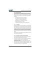
A propos de cette notice d'instructions Veuillez prendre également note de 3 Consignes de sécurité en ce qui concerne la qualification minimale et d'autres conditions relative au personnel. 1.3 Convention de représentation - symboles et signes Pour faciliter la compréhension différentes informations sont représentées ou soulignées dans cette notice d'instructions par les signes suivantes : Réglage correct Indique le réglage correct Pannes Indique les pannes qui peuvent survenir lors d'un mauvais réglage.
A propos de cette notice d'instructions Important Prêtez particulièrement attention à ceci lors d'une étape. Information Des informations supplémentaire par exemple concernant une possibilité d'opération alternative. Séquence Indique quels travaux doivent être effectués avant ou après un réglage. Référence Une référence à une autre partie du document suivra. Sécurité Des consignes de sécurité importantes pour l'utilisateur de la machine sont identifiées de manière spécifique.
A propos de cette notice d'instructions 1.5 Responsabilité Toutes les indications et consignes figurant dans la présente notice d'instructions ont été rédigées en tenant compte de l'état de la technique ainsi que les normes et dispositions en vigueur.
A propos de cette notice d'instructions La machine à coudre ne doit être installée et exploitée que dans des locaux secs et bien entretenus. Si la machine est utilisée dans des locaux qui ne sont pas secs et bien entretenus, d'autres mesures plus étendues pourraient alors s'imposer et doivent être convenues selon EN 60204-31:1999. Uniquement des personnes autorisées sont en droit de manier la machine. Le fabricant décline toute responsabilité pour les dommages issus d'une utilisation non conforme.
A propos de cette notice d'instructions 10 Notice d’instructions 512/532 Version 01.
Spécifications 2 Spécifications La Dürkopp Adler 512 est une machine à commande numérique (CNC) pour la couture automatique des arrêts en points noués. La Dürkopp Adler 532 est un automate pose-boutons. 2.1 Caractéristiques de performance 512 Les dimensions des arrêts standards disponibles sont adaptables et les modifications peuvent être mémoriser.
Spécifications • Un compteur à rebours pour le fil de canette et un compteur pour les pièces cousues quotidiennement sont disponibles. • L'arbre du bras est actionné directement par un moteur à courant continu sans balais. • La vitesse est réglable jusqu'à 3000 min-1 par incréments de 100 min-1. 2.2 Caractéristiques de performance 532 Les dimensions des programmes disponibles sont adaptables et les modifications peuvent être mémoriser.
Spécifications 0,1 mm. • Un compteur à rebours pour le fil de canette et un compteur pour les pièces cousues quotidiennement sont disponibles. • L'arbre du bras est actionné directement par un moteur à courant continu sans balais. • La vitesse est réglable jusqu'à 3000 min-1 par incréments de 100 min-1. • Jusqu'à 10 modèles-types bouton définis par l'utilisateur peuvent être programmés et mémorisés. • En tout, on peut mémoriser 50 modèles-types de boutons sur les 25 touches favorites. 2.
Spécifications Classe 512 532 max. en direction X 40 max. en direction Y 30 max. en direction X 40 max.
Consignes de sécurité 3 Consignes de sécurité Ce chapitre contient des instructions élémentaires pour votre sécurité. Veuillez lire attentivement ces instructions avant de monter, programmer, entretenir ou utiliser la machine. Suivez impérativement les instructions données dans les consignes de sécurité. Ignorer ces instructions peut mener à des blessures graves et à des dégâts matériels. 3.
Consignes de sécurité Installation Le câble de raccordement doit être équipé d'une fiche de secteur homologuée spécifique au pays. Seuls des électriciens qualifiés sont habilités à raccorder la fiche de secteur au câble. Obligations Veuillez respecter les consignes de sécurité et les instructions de l'exploitant préventives aux accidents en vigueur spécifique au pays ainsi que les dispositions légales concernant la sécurité de travail et la protection de l'environnement.
Consignes de sécurité 3.2 Mentions d'avertissement et pictogrammes dans les consignes de sécurité Les mentions d'avertissement sont encadrées par des traits en couleur. Les couleurs indiquent la gravité du danger. Les mentions d'avertissement signalent la gravité du danger : Mentions d'aver- Les mentions d'avertissement et le risque qu'ils décrivent : tissement Mention d'avertissement Risque DANGER Mort ou blessure grave survient. AVERTISSEMENT Mort ou blessure grave peut survenir.
Consignes de sécurité Exemples Exemples de consignes de sécurité dans le texte : DANGER Nature et source du danger Conséquences du non-respect Mesures à prendre pour écarter le danger Voici un avertissement de danger dont le non-respect mène à la mort ou à des blessures graves. AVERTISSEMENT Nature et source du danger Conséquences du non-respect Mesures à prendre pour écarter le danger Voici un avertissement de danger dont le non-respect peut mener à la mort ou à des blessures graves.
Consignes de sécurité ATTENTION Nature et source du danger Conséquences du non-respect Mesures à prendre pour écarter le danger Voici un avertissement de danger dont le non-respect peut mener à des dégâts causés à l'environnement. Notice d’instructions 512/532 Version 01.
Consignes de sécurité 20 Notice d’instructions 512/532 Version 01.
Fonctionnement 4 Fonctionnement 4.1 Enfiler le fil d'aiguille ATTENTION Risque d'accident dû à la pointe de l'aiguille et des parties en mouvement Enfiler le fil d'aiguille uniquement, lorsque la machine à coudre est coupée du secteur. 1. Mettre le cône de fil sur le porte-bobine et faire passer le fil d'aiguille et de crochet à travers le bras de débobinage. Le bras de débobinage doit se trouver horizontalement audessus des cônes de fil. 2.
Fonctionnement 4.2 Régler la tension du fil d'aiguille Fig. 2: Régler la tension du fil d'aiguille ① ② (1) - Élément de prétension (2) - Élément de tension principale Prétension du fil d'aiguille Lorsque l'élément de tension principale (2) est ouvert, une faible tension résiduelle doit être maintenue. La tension résiduelle provient de l'élément de prétension (1).
Fonctionnement Ouvrir l'élément de tension du fil d'aiguille L'élément de tension principale (2) s'ouvre automatiquement lors de la coupure du fil et lorsque les pieds pinceurs se lèvent. 4.3 Régler le régulateur du fil ATTENTION Risque d'accident dû à la pointe de l'aiguille et des parties en mouvement Enfiler le fil d'aiguille uniquement, lorsque la machine à coudre est coupée du secteur. Fig.
Fonctionnement Avec le régulateur de fil (1) on peut ajuster la quantité de fil nécessaire pour la formations des points. Uniquement un régulateur de fil bien réglé peut garantir un excellent résultat de couture. Si le réglage est correct, la boucle du fil d’aiguille sera légèrement tendue avant de glisser sur la partie la plus épaisse du crochet. 1. Desserrer la vis (3). 2. Ajuster la position du régulateur de fil (1).
Fonctionnement 1. Mettre la canette (2) sur l'arbre du dévidoir (3). 2. Faire passer le fil à travers le guide-fil (5) et autour l'élément de tension (6). 3. Bobiner le fil dans le sens antihoraire env. 5 x autour du noyau de la canette (2). 4. Pousser le levier (4) du dévidoir dans la canette. 5. Entamer le processus de couture. Après avoir atteint le taux de remplissage de la canette préréglée (voir Instructions de service), le dévidoir s'arrête automatiquement. 6.
Fonctionnement Fig. 5: Remplacer la canette du fil de crochet ① ⑤ ④ ② ③ (1) - Loquet de la canette (2) - Partie supérieure de la boîte à canette (3) - Coiffe du crochet ⑥ ② ⑦ (4) - Trou (5) - Ressort de tension (6) - Canette (7) - Fente dans la boîte à canette Enlever la canette vide 1. Tirer la coiffe du crochet (3) vers le bas. 2. Soulever le loquet de la canette (1). 3. Enlever la partie supérieure de la boîte à canette (2) avec la canette (6). 4. Enlever la canette vide de sa boîte (2).
Fonctionnement 4.6 Régler la tension du fil de crochet ATTENTION Risque d'accident dû à la pointe de l'aiguille et des parties en mouvement Régler la tension du fil de crochet uniquement, lorsque la machine à coudre est coupée du secteur. Fig. 6: Régler la tension du fil de crochet ① ② ③ (2) - Vis (1) - Ressort de tension glage La tension du fil de crochet doit être générée par le ressort de tension (1).
Fonctionnement 4.7 Remplacer l'aiguille ATTENTION Risque d'accident dû à la pointe de l'aiguille et des parties en mouvement Remplacer l'aiguille uniquement, lorsque la machine à coudre est coupée du secteur. Fig. 7: Remplacer l'aiguille ③ ① (1) - Encoche (2) - Vis ② (3) - Barre à aiguille 1. Desserrer la vis (2) et enlever l'aiguille. 2.
Fonctionnement Endommagement de la pointe du crochet, endommagement de l'aiguille 4.8 Régler le positionneur de boutons de la pince bouton (classe 532) ATTENTION Risque d'accident dû à la pointe de l'aiguille et des parties en mouvement Remplacer les aiguilles uniquement, lorsque la machine à coudre est coupée du secteur. Fig. 8: Régler le positionneur de boutons - pince standard ① ④ ② ③ (1) - Positionneur de boutons gauche (2) - Loquet (3) - Vis moletée (4) - Positionneur de boutons droit Fig.
Fonctionnement Le bouton doit pouvoir être glissé et ajusté facilement dans le positionneur de boutons de la pince bouton. En même temps il doit être serré fermement afin de ne pas bouger lors que la pièce à coudre est insérée. La butée (2) règle la largeur de l'ouverture du postionneur de boutons. 1. Allumer la machine à coudre automatique. 2. Appuyer sur la touche Ready. La pince est levée, la pédale est prête à coudre. 3. Appuyer sur la touche Ready. La pince reste levée, la pédale est bloquée. 4.
Fonctionnement La pince bouton peut être équipée en option d'un générateur de tiges (3). Rentrer ou sortir le générateur de tiges par pivotement 1. Rentrer ou sortir le levier pivotant (2) avec le générateur de tiges (3) manuellement par pivotement lorsque la pince bouton est levée. Régler la longueur de tige 1. Tourner la vis de réglage (1). • Dans le sens horaire = Tige plus longue. • Dans le sens antihoraire = Tige plus courte. Notice d’instructions 512/532 Version 01.
Fonctionnement Régler le générateur de tiges La position du générateur de tiges (3) peut être ajustée aux différents diamètres des boutons. 1. Desserrer la vis (4). 2. Ajuster le générateur de tiges dans la direction de l'axe Y. 3. Resserrer la vis (4). 4.10 Coudre Déroulement d'opérations et fonctions lors de la couture Processus de couture Maniement / Commentaire Avant de commencer la couture Pédale en position de repos. La machine à coudre est arrêtée. L'aiguille est en haut, les pinces sont en haut.
Fonctionnement 4.11 Service après-vente Votre interlocuteur pour la réparation ou d'autres soucis avec votre machine: Dürkopp Adler AG Potsdamer Str.190 33719 Bielefeld Tél. +49 (0) 180 5 383 756 Fax +49 (0) 521 925 2594 Courriel: service@duerkopp-adler.com Internet: www.duerkopp-adler.com Notice d’instructions 512/532 Version 01.
Fonctionnement 34 Notice d’instructions 512/532 Version 01.
Réglages par le logiciel 5 Réglages par le logiciel 5.1 Panneau de commande Fig. 11: Panneau de commande ⑤ ⑥ ⑦ ⑧ ⑨ ⑩ ⑪ ④ ③ ② ⑫ ① Touches de commande : Touche / Voyant Pos. DEL Fonction (1) Touche USB avec DEL Mémorise / charge schémas de couture depuis / sur une clé USB. (2) Touche Pince fil d'aiguille avec DEL Attache le fil d'aiguille lors du premier point de couture.
Réglages par le logiciel Touche / Voyant Pos. DEL Fonction (4) Touche Reset Efface des erreurs et reconstitue les réglages. (5) Touche Ready avec DEL Changement entre mode de programmation et mode de couture. DEL allumé = Mode de couture DEL éteint = Mode de programmation (6) DEL Erreur DEL allumé = Erreur (7) Écran Programme Affiche les paramètres.
Réglages par le logiciel 5.3 Effectuer une passe de référence de la machine 1. Appuyer sur la touche Ready. Le voyant DEL de la touche s'allume. 2. Appuyer sur la touche Ready. Le voyant de la touche s'éteint. 5.4 Sélectionner un schéma de couture ATTENTION Endommagements de l'aiguille, si la taille du schéma de couture ne correspond pas au pied pinceur. Vérifier le pied pinceur et l'ajuster si nécessaire.
Réglages par le logiciel 5.5.2 Mise à l'échelle de l'axe Y 1. Appuyer sur la touche Sélection jusqu'à ce que le voyant DEL du symbole axe Y s'allume. 2. Appuyer sur les touches +/- Fonction, jusqu'à ce que la valeur de l'axe Y est atteinte. 100 % correspondent aux dimensions du schéma de couture sélectionné. 5.5.3 Convertir la distance boutonnière (classe 532) La distance boutonnière est préréglée à 3,4 mm (3,4 mm = 100 %). On peut ajuster la distance boutonnière en changeant la valeur de pourcentage.
Réglages par le logiciel distance boutonnière [mm] Valeur [%] distance boutonnière [mm] Valeur [%] distance boutonnière [mm] Valeur [%] 2.6 76 4.5 132 6.4 188 2.7 79 4.6 135 6.5 191 2.8 82 4.7 138 5.5.
Réglages par le logiciel 2. Appuyer sur la touche Ready pour valider le schéma de couture. Le voyant DEL de la touche Ready est allumé. 3. Appuyer la pédale vers l'avant. La pince descend. 4. Appuyer sur les touches +/- Fonction pour coudre 1 point à la fois. L'écran Fonction affiche le nombre de points courants. 5. Appuyer sur la touche Reset. La pince se lève. 6. Appuyer sur la touche Sélection, jusqu'à ce que le voyant DEL du symbole Forme du schéma de couture s'allume. 5.
Réglages par le logiciel Le processus de bobinage démarre. 6. Pour arrêter le processus de bobinage, appuyer brièvement la pédale complètement en avant. 7. Appuyer sur la touche Ready. Le voyant DEL s'éteint, la pince est soulevée. Notice d’instructions 512/532 Version 01.
Réglages par le logiciel 5.10 Coudre Condition préalable : • La machine est en mode de couture, le voyant DEL de la touche Ready est allumé. • L'aiguille est en place. • Le fil d'aiguille est enfilé. • Le schéma de couture est sélectionné. 1. Mettre l’ouvrage en place. 2. Appuyer la pédale vers l'avant dans la première position. La pince descend. Lorsque la pédale est relâchée, la pince est soulevée. 3. Appuyer brièvement la pédale complètement en avant. Le processus de couture démarre.
Réglages par le logiciel 5.12 Interrompre la couture 1. Appuyer sur la touche Reset ou appuyer la pédale en arrière. Le processus de couture est en pause, l'écran affiche le message d'erreur E-50. 2. Pour continuer la couture, appuyer sur la touche Reset ou la pédale en avant. 5.13 Bloquer les schémas de couture standards Il est possible de bloquer des schémas de couture standards afin qu'ils ne soient plus affichés.
Réglages par le logiciel Accès rapide aux schémas de couture (par combinaison de touches) No. de mémoire Combin. No. de de mémoire touches Combin. No. de de mémoire touches Combinaison de touches No.
Réglages par le logiciel • Appuyer sur la touche Sélection, jusqu'à ce que le voyant DEL du symbole axe Y clignote. • Appuyer sur les touches +/- Fonction et régler les valeurs : -4/+4. 8. Appuyer sur la touche Ready pour valider les réglages. 9. Appuyer sur la touche Memory pour quitter le mode mémoire. 10. Vérifier le schéma de couture ( 5.7 Vérifier le schéma de couture, p. 39). 5.14.2 Coudre avec les touches mémoire 1. Appuyer sur la touche / combinaison de touches. 2. Appuyer sur la touche Ready. 3.
Réglages par le logiciel de mémoire P1 ~ P50, la machine peut également coudre les schémas de couture mémorisés aux emplacements C01 ~ C25. Condition préalable : • La machine se trouve au mode de programmation, le voyant DEL de la touche Ready est éteint. 1. Appuyer sur les touches Memory et P3 simultanément. 2. Appuyer sur les touches +/- Programme pour sélectionner un emplacement de mémoire (C01 ~ C25). 3. Appuyer sur la touche Ready pour mémoriser la séquence des schémas de couture. 4.
Réglages par le logiciel couture, par exemple <1.1>, l'écran Fonction affiche le numéro du schéma de couture. 3. Appuyer brièvement la pédale complètement vers l'avant. Le schéma de couture est cousu. L'écran Programme affiche après la fin de couture la prochaine séquence de schémas de couture, par exemple <1.2>, l'écran Fonction affiche le prochain numéro du schéma de couture, ainsi de suite. 4.
Réglages par le logiciel 1. Appuyer sur la touche Ready. Le voyant DEL de la touche s'allume. L'unité de contrôle se trouve en mode de couture. 2. Interrupteur principal sur ARRÊT. NOTA BENE Si on éteint la machine à coudre sans avoir appuyé au préalable la touche Ready, les valeurs modifiées ne seront pas mémorisées. 5.19 Éditer les paramètres dans la mémoire 5.19.
Réglages par le logiciel 5.19.2 Éditer les paramètres du niveau M2 Condition préalable : • La machine se trouve au mode de programmation, le voyant DEL de la touche Ready est éteint. 1. Appuyer sur la touche Memory pendant 6 secondes. L'unité de contrôle fait deux fois "bip", le voyant DEL de la touche s'allume. L'écran Programme affiche le numéro de paramètre, l'écran Fonction affiche les valeurs. 2. Appuyer sur la touche +/- Programme pour sélectionner d'autres paramètres. 3.
Réglages par le logiciel 5.20 Remettre les paramètres au réglage d'usine Condition préalable : • La machine se trouve au mode de programmation, le voyant DEL de la touche Ready est éteint. 1. Appuyer sur la touche Memory pendant 6 secondes. Le voyant DEL de la touche s'allume. 2. Sélectionner le numéro de paramètre U098 par les touches +/- Programme. 3. Appuyer sur la touche Ready. 4. Sélectionner la valeur de fonction 1 par les touches +/- Fonction. 5. Appuyer sur la touche Sélection.
Réglages par le logiciel 5.21 Éditer des schémas de couture ailleurs ATTENTION Endommagements de la pince, si les dimensions du champ de couture ne correspondent pas aux pieds pinceur. Les schémas de couture peuvent être crées ou édités sur un ordinateur externe, par exemple avec MS Excel ou un éditeur de texte. Chaque ligne correspond à une abscisse et ordonnée. Le schéma de couture a des dimensions maximales de 400 x 300 x 1/10 mm. Des valeurs négatives ou des valeurs décimales ne sont pas admises.
Réglages par le logiciel Fig. 12: Coordonnées de contour en MS-Excel ou éditeur de texte ① ② (1) - Point initial/ Premier point de couture (2) - Point final/ Dernier point de couture Fig. 13: Exemple d'un schéma de couture ② ① (1) - Point initial/ Premier point de couture (2) - Point final/ Dernier point de couture 1. Saisie des coordonnées de contour effectuées par MS-Excel ou éditeur de texte. Les coordonnées sont saisies avec une précision de 0,1 mm et séparées par virgule.
Réglages par le logiciel Important Lorsqu'on utilise un éditeur de texte, la dernière ligne de coordonnées doit être terminée par un retour à la ligne, de sorte que le curseur se trouve dans la prochaine ligne vide. 2. Mémoriser le fichier : • Nom du fichier : HSR2000 ~ HSR2099 • Format de fichier : .CSV 3. Mémoriser le fichier sur une clé USB. Information Il est également possible de créer des schémas de couture par DA-CAD 5000 et de les mémoriser en tant que fichier CSV.
Réglages par le logiciel 5.22 Utiliser une clé USB Jusqu'à 10 schémas de couture nouveaux peuvent être mémoriser sur l'unité de contrôle par une clé USB. Condition préalable : • La machine se trouve au mode de programmation, le voyant DEL de la touche Ready est éteint. 1. Insérer la clé USB dans le port USB de l'unité de contrôle. L'unité de contrôle émet un bref "bip". 2. Appuyer sur la touche USB. Le voyant DEL de la touche s'allume, l'écran Programme affiche le numéro de paramètre U01. 3.
Réglages par le logiciel Mémoriser un schéma de couture depuis l'unité de contrôle sur la clé USB : Chiffre 2 1. Régler le chiffre 2 avec les touches +/- Fonction. 2. Appuyer sur la touche Sélection pour mémoriser le schéma de couture sur la clé USB (HSW2001.scv = U01 ~ HSW2010.scv = U10). 3. Appuyer sur la touche Sélection pour valider la mémorisation. L'écran Fonction affiche la valeur ok, l'unité de contrôle émet un "bip", le schéma de couture est mémorisé. 4. Appuyer sur la touche Reset 2 fois.
Réglages par le logiciel Le voyant du symbole axe Y s'allume, l'écran Fonction affiche la valeur pour l'axe Y. 5. Saisir avec les touches +/- Fonction les coordonnées du premier point de couture pour l'axe Y. 6. Sélectionner le prochain point de couture avec les touches +/- Programme. 7. Répéter les pas 3 à 5 pour tous les autres points de couture. 8. Appuyer sur la touche Ready pour mémoriser le schéma de couture édité. 9. Appuyer sur la touche Reset. Le voyant de la touche s'éteint. 10.
Réglages par le logiciel Message d'erreur Commentaire Cause possible Dépannage E 4 2 Erreur La longueur de couture est Agrandissement au dessus de 10 mm • Appuyer sur la touche Reset. • Vérifier le schéma de couture et les échelles X/ Y. E 4 5 Erreur Données du schéma de couture Données du schéma de couture ne sont pas acceptées • Appuyer sur la touche Reset. • Vérifier la mémoire ROM. E 5 0 Interruption Touche Reset appuyée pendant la couture. Machine à coudre s'arrête.
Réglages par le logiciel Message d'erreur Commentaire Cause possible Dépannage E 5 0 5 Erreur de lecture Clé USB pas reconnue clé USB • Interrupteur principal sur ARRÊT. • Interrupteur principale sur MARCHE. • Insérer clé USB encore une fois. E 5 0 6 Erreur de lecture Lecture de U01 ~ U10 pas clé USB possible. • Interrupteur principal sur ARRÊT. • Interrupteur principale sur MARCHE. • Insérer clé USB encore une fois.
Réglages par le logiciel Message d'erreur Commentaire Cause possible Dépannage E 5 5 0 Erreur d'écriture Erreur de transmission de données mémoire Flash E 5 5 1 Erreur de processus interne E 7 7 0 7 3 5 Erreur signal du Encodeur / moteur ne reçoit • Vérifier encodeur / moteur pas de signal moteur. E 7 3 6 Erreur rotation du moteur Le moteur s'arrête après un temps / l'encodeur ne reçoit pas de signal • Vérifier encodeur / moteur.
Réglages par le logiciel Message d'erreur Commentaire Cause possible Dépannage • Interrupteur principal sur ARRÊT. • Vérifier le capteur. E 9 1 3 Erreur Recherche capte-fil Capteur capte-fil ne réagit pas E 9 1 4 Erreur Moteur capte-fil Moteur capte-fil ne • Interrupteur principal sur fonctionne pas correctement ARRÊT. • Vérifier moteur et connexions. 5.24 Installer le logiciel par clé USB ATTENTION Endommagent de la machine par interruption du téléchargement.
Réglages par le logiciel 5.24.1 Installer le logiciel principal 1. Activer l'unité de contrôle. 2. Insérer la clé USB. 3. Appuyer sur la touche USB et attendre pour environ 3 secondes. 4. Appuyer sur la touche Memory. 5. Régler la valeur 5 avec les touches +/- Fonction à l'écran Fonction. 6. Appuyer sur la touche Sélection. Le de téléchargement vers l'unité de contrôle commence. Important Lorsque l'écran Fonction n'affiche plus aucune valeur, le téléchargement est accompli.
Réglages par le logiciel 5.24.3 Régler le paramètre U085 (classe 532) Après avoir téléchargé une nouvelle version de logiciel, le paramètre U085 doit être réglé pour l'automate pose-boutons. Condition préalable : • La machine se trouve au mode de programmation, le voyant DEL de la touche Ready est éteint. 1. Appuyer sur la touche Memory pendant 6 secondes. Le voyant DEL de la touche s'allume. 2. Sélectionner le numéro de paramètre U085 par les touches +/- Programme. 3. Appuyer sur la touche Ready. 4.
Entretien 6 Entretien Ce chapitre décrit les travaux d'entretien à effectuer régulièrement afin de prolonger la durée de vie et de maintenir une haute qualité de couture. Les travaux d'entretien plus approfondis doivent être effectués uniquement par un personnel spécialisé et qualifié, Instructions de service.
Entretien toutes les 8 heures de service avec un pistolet à air comprimé ou un pinceau. Avec un matériel de couture qui produit beaucoup de poussière, il faut nettoyer la machine plus souvent. Une machine à coudre propre vous met à l’abri de pannes et perturbations ! Endroits nécessitant un nettoyage particulier: • • • • • Endroit en dessus de la plaque à aiguille (1) Endroit autour du crochet (2) Boîte à canette et son intérieur Coupe-fil Endroit autour de l'aiguille Fig.
Entretien 6.2 Lubrifier AVERTISSEMENT Risques de blessure dues au contact avec l'huile ! Le contact avec l'huile peut provoquer des irritations, éruptions, allergies ou lésions cutanées. Éviter TOUT contact prolongé avec l'huile. Après CHAQUE contact lavez soigneusement les parties de la peau exposé à l'huile. ATTENTION Danger de dégâts causés à l'environnement par des huiles usées ! Le maniement inapproprié des huiles usées peut provoquer de graves dégâts à l'environnement.
Entretien 6.2.1 Vérifier le niveau d'huile La machine à coudre automatique est pourvue d’un graissage central par mèches. Les points de graissage sont alimentés depuis le réservoir d’huile (1). Fig. 16: Faire le niveau d'huile ② ① (1) - Réservoir d'huile (2) - Ouverture de remplissage Le niveau d'huile ne doit pas descendre au-dessous du trait-repère rouge inférieur du réservoir d'huile (1) ou dépasser le trait-repère rouge supérieur. 1.
Entretien 6.2.2 Graissage Les parties mobiles de la machine doivent être graissé convenablement pour maintenir le bon fonctionnement de la machine. Points de graissage à la face arrière de la machine Fig. 17: Graissage ③ ① ② (1) - Came (2) - Feutre (3) - Articulations 1. Mettre une quantité suffisante de graisse sur le feutre (2) pour lubrifier la partie extérieure de la came (1). 2. Mettre un peu de graisse sur les articulations (3) pour les garder souples.
Entretien Fig. 18: Lubrification ④ ⑥ ⑤ (4) - Galet (5) - Gorge de guidage (6) - Articulations 1. Mettre un peu de graisse depuis l'extérieur sur la gorge de guidage intérieure (5) et le galet (4). 2. Mettre un peu de graisse sur les articulations (6). 68 Notice d’instructions 512/532 Version 01.
Entretien Points de graissage à la tête de machine Fig. 19: Graissage ⑦ ⑧ ⑨ (7) - Guidon du levier de fil (8) - Rainure ⑩ (9) - Tête cruciforme arrière (10) - Douilles 1. Mettre de la graisse sur la tête cruciforme arrière (9) et les douilles (10). 2. Graisser la rainure (8). 3. Graisser le guidon du levier de fil (7). Notice d’instructions 512/532 Version 01.
Entretien 70 Notice d’instructions 512/532 Version 01.
Schémas de couture 7 Schémas de couture 7.1 Schémas de couture standards pour la classe 512 N° 1 Diagramme des points de couture Nombre des points de couture Dimensions (mm) X x Y 42 16 x 2 2 10 x 2 3 16 x 2,5 4 24 x 3 5 28 6 7 10 x 2 16 x 2 36 8 10 x 2 16 x 2,5 9 56 24 x 3 10 64 24 x 3 11 21 6 x 2,5 12 28 6 x 2,5 13 36 6 x 2,5 14 14 8x2 Notice d’instructions 512/532 Version 01.
Schémas de couture Nombre des points de couture Dimensions (mm) X x Y 15 21 8x2 16 28 8x2 17 21 10 x 0,1 18 28 10 x 0,1 N° Diagramme des points de couture 19 25 x 0,1 20 36 25 x 0,1 21 41 25 x 0,1 22 44 35 x 0,1 23 28 4 x 20 24 36 25 42 26 56 72 Notice d’instructions 512/532 Version 01.
Schémas de couture Nombre des points de couture Dimensions (mm) X x Y 27 18 0,1 x 20 28 21 0,1 x 10 N° Diagramme des points de couture 29 0,1 x 20 30 28 0,1 x 20 31 52 10 x 7 32 63 12 x 7 33 24 10 x 6 34 31 12 x 6 35 48 7 x 10 36 48 7 x 10 37 90 24 x 3 Notice d’instructions 512/532 Version 01.
Schémas de couture Nombre des points de couture Dimensions (mm) X x Y 38 28 8x2 39 28 Ø 12 40 48 41 29 2,5 x 20 42 39 2,5 x 25 43 45 2,5 x 25 44 58 2,5 x 30 45 75 2,5 x 30 46 42 2,5 x 30 47 91 Ø8 48 99 49 148 50 164 N° 74 Diagramme des points de couture Notice d’instructions 512/532 Version 01.
Schémas de couture 7.
Schémas de couture 76 Notice d’instructions 512/532 Version 01.
Installation 8 Installation AVERTISSEMENT Risque de blessure ! Seulement un personnel qualifié est autorisé à assembler et installer la machine. Portez des gants et des chaussures de protection pour déballer et installer la machine. 8.1 Vérifier l'étendue de la livraison L’étendue de la livraison dépend de votre commande. 1. Vérifier que le contenu de la livraison est au complet.
Installation de table • Les feuillards de cerclage et les lattes retenant le bâti. 78 Notice d’instructions 512/532 Version 01.
Installation 8.3 Assemblage 8.3.1 Vérifier les dessus de table ATTENTION Risque de blessure dû à une capacité portante insuffisante pour un dessus de table artisanal Assurez-vous que le dessus de table possède la capacité portante et la solidité nécessaire. Les découpures des dessus de table artisanaux doivent avoir mesures indiquées dans le dessin (voir annexe). 8.3.2 Monter le bâti Fig. 20: Monter le bâti ① ② (1) - Vis de réglage (2) - Pédale Notice d’instructions 512/532 Version 01.
Installation Assembler l'ossature du bâti. 1. Tourner la vis de réglage (1) pour la stabilité du bâti. Les 4 pieds du bâti doivent reposer sur le sol. 2. Visser la pédale (2) sur la traverse du bâti (3) 3. Pousser la pédale (2) pour la centrer sur la traverse du bâti (3). Pour un réglage facile la traverse du bâti est pourvue de trous oblongs. 8.3.3 Compléter le dessus de table Fig.
Installation Fig. 22: Compléter le dessus de table ! ② ① (1) - Vis (2) - Boîtier de commande 1. Poser le boîtier de commande (2) sur la face inférieure de la table. 2. Visser le boîtier de commande (2) avec 3 vis (1), rondelles, circlips et écrous sur la face inférieure de la table. 8.3.4 Monter le support pour la tête de machine Fig. 23: Monter le support pour la tête de machine ① ② (1) - Support pour la tête de Notice d’instructions 512/532 Version 01.
Installation 1. Introduire le support pour la tête de machine (1) dans le trou (2) du dessus de table. 8.3.5 Régler la hauteur de la table de travail Fig. 24: Régler la hauteur de la table de travail ① ② (1) - Cadran gradué (2) - Vis La table de travail peut avoir une hauteur entre 750 mm et 950 mm (mesurée entre le sol et le bord supérieur du dessus de table). La hauteur du bâti doit correspondre à la taille physique de l'opérateur. 1. Desserrer les vis (2) sur les deux barres du bâti. 2.
Installation 8.3.6 Mettre la tête de machine en place Fig. 25: Mettre la tête de machine en place ① ② ③ (1) - Support de fixation (2) - Support de fixation (3) - Machine à coudre automatique ④ ⑤ (4) - Vis (5) - Étrier 1. Poser la machine à coudre (3) sur le dessus de table. 2. Fixer la machine à coudre (3) à gauche et à droite avec les supports de fixation (1) et (2). A cette fin, visser les deux supports de fixation avec les vis (4), l'étrier (5) et les écrous.
Installation 8.3.7 Monter le carter d'huile Fig. 26: Monter le carter d'huile ① ② ③ ④ ⑥ ⑤ (1) - Vis (2) - Support de fixation (3) - Conduite d'huile (4) - Appui en caoutchouc (dans le carter d'huile) 1. Introduire le support de fixation (2) dans le trou du dessus de table (6) et le fixer avec les 3 vis (1). 2. Visser le carter d'huile (5) au support de fixation (2). 3. Introduire la conduite d'huile (3) dans le carter d'huile (5). 4. Poser les appuis en caoutchouc (4) dans le dessus de table (6).
Installation 8.3.8 Connexion électrique DANGER Risque d'électrocution ! L'exposition au courant électrique peut provoquer des blessures mortelles. UNIQUEMENT du personnel électricien qualifié ou des personnes ayant reçues une formation adéquate peuvent effectuer des travaux sur l'équipement électrique. Lors des travaux sur l'équipement électrique, TOUJOURS débrancher la fiche d'alimentation. 8.3.
Installation 8.3.11 Monter le capot de recouvrement Fig. 28: Monter le capot de recouvrement ① ② (1) - Capot de recouvrement (2) - Vis 1. Visser le capot de recouvrement (1) avec 4 vis (2) à la tête de la machine. 8.3.12 Monter la protection des yeux Fig. 29: Monter la protection des yeux ② ① (1) - Protection des yeux (2) - Vis 1. Visser la protection des yeux (2) avec 2 vis (1) à la tête de la machine. 86 Notice d’instructions 512/532 Version 01.
Installation 8.4 Fixer le rack de boutons (classe 532) Fig. 30: Fixer le rack de boutons ③ ① ② (1) - Vis (2) - Support de fixation (3) - Rack de boutons 1. Visser le support de fixation (2) au dessus de table. 2. Introduire le rack de boutons (3) dans le support de fixation (2) et fixer le par un vis (1). Notice d’instructions 512/532 Version 01.
Installation 8.5 Essai de couture Après achèvement des travaux d’installation, effectuer un test de couture. ATTENTION Risque d'accident dû à la pointe de l'aiguille et des parties en mouvement N’enfiler les fils d’aiguille et du crochet, qu’après avoir coupé la machine à coudre du secteur. 1. Enficher la fiche de secteur. 2. Mettre l'interrupteur principal sur ARRÊT. 3. Enfiler le fil de canette. 4. Mettre l'interrupteur sur MARCHE. 5. Remplir la canette à une vitesse moyenne. 6.
Mise au rebut 9 Mise au rebut La machine ne doit pas être jetée avec les ordures ménagères. Elle doit être mise au rebut de manière correctement selon la réglementation de votre pays. ATTENTION Danger de dégâts causés à l'environnement par des huiles usées ! Mise au rebut ! Une mise au rebut inappropriés de la machine peut provoquer de graves dégâts à l'environnement. TOUJOURS respecter les dispositions légales concernant la mise au rebut.
Mise au rebut 90 Notice d’instructions 512/532 Version 01.
Annexe 10Annexe Notice d’instructions 512/532 Version 01.
Annexe 92 Notice d’instructions 512/532 Version 01.
Subject to design changes - Printed in Germany - © Dürkopp Adler AG - Original Instructions - 0791 512740 FR - 01.0 - 07/2015 DÜRKOPP ADLER AG Potsdamer Straße 190 33719 Bielefeld GERMANY Phone +49 (0) 521 / 925-00 E-mail marketing@duerkopp-adler.com www.duerkopp-adler.