DA_512-211_deen_12-2013.qxd:DA-6-pages.qxd 512/532 04.12.
All rights reserved. Property of Dürkopp Adler AG and protected by copyright. Any reuse of this content, including extracts thereof, is prohibited without the prior written approval of Dürkopp Adler AG.
Contents 1 About this service manual ......................................................... 3 1.1 1.2 1.3 1.4 Scope of the service manual ........................................................ 3 Representation conventions – symbols and characters ............... 3 Other documents .......................................................................... 4 Liability.......................................................................................... 4 2 Safety information ....................
Contents 11.5.3 Converting the buttonhole gap (class 532) ................................. 36 11.5.4 Converting the backtack dimensions (class 512) ....................... 36 11.6 Setting the speed........................................................................ 37 11.7 Checking the sewing pattern ...................................................... 37 11.8 Changing the sewing pattern ...................................................... 37 11.9 Winding...........................................
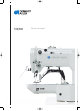
About this service manual 1 About this service manual This manual for the 512/532 sewing machines has been compiled with the utmost care. It contains information and notes in order to make long-term and reliable operation possible. 1.1 Scope of the service manual This manual describes the setting and maintenance work for sewing machines 512/532. It applies to all submodels. The intended use and set-up is described in the operating manual. 1.
About this service manual Information Additional information, e.g. on alternative operating possibilities. Observe order Specifies the work to be performed before or after a setting. References Reference to another section in the manual. Safety Important warnings for the machine operator are specially designated. Since safety is of particular importance, hazard symbols, levels of danger and their signal words are described separately in 3 Safety information.
Safety information 2 Safety information This section contains basic information for your safety. Read the information carefully before setting up, programming, maintaining or operating the machine. Make sure to follow the information included in this section. Failure to do so can result in serious injury and damage to the machine. 2.1 Basic safety instructions Only authorized personnel should use the machine. Anyone working on the machine should read the operating manual first.
Safety information Only qualified specialists may perform maintenance work and repairs. Anyone maintaining or adjusting the machine must have read the service manual first. Safety equipment should not be removed or deactivated. If this cannot be avoided for a repair operation or service setting, the safety equipment must be refitted and put back into service immediately afterwards. Only qualified electrical specialists may perform work on electrical equipment.
Safety information Symbols The following symbols indicate the type of risk to personnel: Symbol Type of danger General risk Risk of electric shock Risk of puncturing Risk of crushing Examples Examples of the layout of the warnings in the text: DANGER Type and source of risk Consequences of non-observance Measures for avoiding the risk This is what a warning looks like for a hazard that will result in serious injury or even death if not complied with.
Safety information CAUTION Type and source of risk Consequences of non-observance Measures for avoiding the risk This is what a warning looks like for a hazard that could result in moderate or minor injury if the warning is not complied with. CAUTION Type and source of risk Measures for avoiding the risk This is what a warning looks like for a hazard that could result in environmental damage if not complied with.
Work principles 3 Work principles 3.1 Order of settings Observe order Always adhere to the specified sequence for the individual setting steps. Always observe all notes marked with a and follow-up settings. in the margin on prerequisites ATTENTION Machine damage possible due to incorrect order. Always adhere to the working order specified in this manual. 3.
Work principles 3.3 Removing the covers WARNING Risk of injury! Crushing injuries from moving parts. Switch the sewing machine off before you remove the covers or refit them. In many types of setting work, you will have to remove the machine covers first in order to access the components. Described here is how to remove the individual covers and how to reattach them. Just the cover that needs to be removed is then specified in the text for that particular type of setting work. 3.3.
Work principles 3.3.2 Removing and fitting the head cover Figure 2: Removing and fitting the head cover ① ② (1) - Screw (2) - Eye guard ③ (3) - Head cover Removing the head cover 1. Unscrew the eye guard (2). 2. Loosen both screws (1). 3. Remove the head cover (3). Fitting the head cover 1. Fit the head cover (3). 2. Tighten both screws (1). 3. Tighten the eye guard (2). 3.3.
Work principles Removing the arm cover 1. Loosen all 6 screws (1). 2. Remove the arm cover (2). Fitting the arm cover 1. Fit the arm cover (2). 2. Tighten all 6 screws (1) firmly in place. 3.3.4 Removing and fitting the right-hand side cover Figure 4: Removing and fitting the right-hand side cover ① ② (1) - Screw (2) - Right-hand side cover Removing the right-hand side cover 1. Loosen both screws (1). 2. Remove the right-hand side cover (2). Fitting the right-hand side cover 1.
Work principles 3.3.5 Removing and fitting the left-hand side cover Figure 5: Removing and fitting the left-hand side cover ① (1) - Screw ② (2) - Left-hand side cover Removing the left-hand side cover 1. Loosen all 3 screws (1). 2. Remove the left-hand side cover (2). Fitting the left-hand side cover 1. Fit the left-hand side cover (2). 2. Tighten all 3 screws (1) firmly in place. 3.3.
Work principles Removing the rear cover 1. Loosen all 4 screws (1) on the rear cover (2). 2. Remove the rear cover (2). Fitting the rear cover 1. Fit the rear cover (2). 2. Tighten all 4 screws (1) on the rear cover (2) firmly in place. 3.3.7 Opening and closing the hook flap Figure 7: Opening and closing the hook flap ① (1) - Hook flap Opening the hook flap Fold down the hook flap (1). Closing the hook flap Fold up the hook flap (1). 14 Service manual 512/532 Version 00.
Work principles 3.3.8 Removing and inserting the throat plate Figure 8: Removing and inserting the throat plate I ① ② ③ ④ (1) - Springs of the fabric clamp (2) - Clamp feet (3) - Screw (4) - Work surface Removing the throat plate 1. Remove both springs of the fabric clamp (1). 2. Raise both clamp feet (2). 3. Loosen the screw (3) for the work surface (4). 4. Remove the work surface (4).
Work principles 5. Open the hook flap ( Section 3.3.7, page 14). 6. Loosen the screw (6). 7. Unhinge the thread puller blade connecting rod (5). Figure 10: Removing and inserting the throat plate III ⑧ ⑦ (7) - Throat plate (8) - Screw 8. Loosen all 4 screws (8). 9. Remove the throat plate (7) upwards. Inserting the throat plate Figure 11: Removing and inserting the throat plate IV ⑨ (9) - Connecting rod pin for needle thread clamp 1. Insert the throat plate (7) from above.
Work principles 5. Close the hook flap ( Section 3.3.7, page 14). 6. Fit the work surface (4). 7. Tighten the screw (3) for the work surface (4) firmly in place. 8. Mount both springs of the fabric clamp (1). 3.4 Surfaces on shafts Screw onto the surface Figure 12: Surfaces on shafts 1 2 (1) - Surface (2) - Shaft Some shafts have flat surfaces at those points where the components are screwed on. This strengthens the connection and setting work is made easier.
Work principles 18 Service manual 512/532 Version 00.
Adjusting the light barriers 4 Adjusting the light barriers WARNING Risk of injury! Crushing injuries from moving parts. Switch off the sewing machine before adjusting the light barriers. 4.1 Light barrier sensor disks The light barrier sensor disks are used as a reference for positioning by the control unit. Checking the correct setting The 180° disk points to the front and its lower edge is precisely lined up with the light barriers slots.
Adjusting the light barriers 4.2 Adjusting the left and right switching flags The switching flags are used as reference by the control unit for the position of the clamps in an X and Y-direction. Checking the correct setting The clamps are centered in both an X and Y-direction. Faults caused by an incorrect setting • Damage to the needle • Incorrect needle position Cover • Remove the right-hand side cover ( Section 3.3.4, page 12). • Remove the left-hand side cover ( Section 3.3.5, page 13).
Adjusting the light barriers Adjusting steps 1. Loosen the screw (1). 2. Adjust the switching flag (2) accordingly. 3. Set the zero point via the control unit. 4. Tighten the screw (1). 5. Reference the machine. 4.3 Thread clamp switching flag The thread clamp switching flag is used as reference by the control unit for the thread clamp. The switching flag is located underneath the throat plate to the right and is factory set. Service manual 512/532 Version 00.
Adjusting the hook and needle bar 5 Adjusting the hook and needle bar The following 3 settings must be coordinated: • Height of the needle bar • Loop stroke position and needle guard • Hook clearance to the needle 5.1 Adjusting the needle bar height WARNING Risk of injury! Crushing hazard and puncturing injuries due to moving and sharp parts. Switch off the sewing machine before adjusting the height of the needle bar. The needle bar has 4 marker lines which serve as an adjusting aid.
Adjusting the hook and needle bar 5.2 Adjusting the loop stroke and needle guard WARNING Risk of injury! Crushing hazard and puncturing injuries due to moving and sharp parts. Switch off the sewing machine before adjusting the height of the needle bar. Loop stroke The loop stroke is the path length from the lower dead center of the needle bar to the position where the hook is in the loop stroke position.
Adjusting the hook and needle bar Cover • Open the hook flap ( Section 3.3.7, page 14). Figure 18: Adjusting the loop stroke and needle guard ① ⑤ ② 512 ③ ④ (1) - Hook tip (2) - Hook (3) - Driver (4) - Screw 532 ⑥ ⑦ (5) - Needle (6) - Marker line for class 512 (7) - Marker line for class 532 Adjusting steps 1. Use the handwheel to adjust the needle bar so that the corresponding marker line (6/7) is aligned with the needle bar bush. 2. Loosen the screw (4). 3. Remove the cover ring.
Adjusting the hook and needle bar 5.3 Adjusting the distance between the hook tip and needle WARNING Risk of injury! Crushing hazard and puncturing injuries due to moving and sharp parts. Switch off the sewing machine before adjusting the distance between the hook tip and needle. Cover • Open the hook flap ( Section 3.3.7, page 14).
Adjusting the thread trimmer 6 Adjusting the thread trimmer For the thread trimmer to work correctly, you must set the thread puller blade and the counter blade. WARNING Risk of injury! Crushing hazard and puncturing injuries due to moving and sharp parts. Switch off the sewing machine before adjusting the blades. Faults caused by an incorrect setting • Threads are not cut • Threads are cut too long Cover • Remove the throat plate ( Section 3.3.8, page 15).
Adjusting the height of the fabric clamp lift 7 Adjusting the height of the fabric clamp lift WARNING Risk of injury! Crushing hazard and puncturing injuries due to moving and sharp parts. Switch off the sewing machine before adjusting the fabric clamp lift. The following maximum heights apply when adjusting the fabric clamp lift: • Max. height for class 512: 17 mm • Max. height for class 532: 13 mm Cover Remove the arm cover ( Section 3.3.3, page 11).
Adjusting the height of the fabric clamp lift Adjusting the fabric clamping feet (class 512) Faults caused by an incorrect setting • The two fabric clamping feet do not raise and lower synchronously. Figure 22: Adjusting the fabric clamping feet ① (1) - Screw Adjusting steps 1. Loosen the screws (1). 2. Align the fabric clamping feet synchronously. 3. Tighten the screws (1). 28 Service manual 512/532 Version 00.
Adjusting the thread wiper 8 Adjusting the thread wiper WARNING Risk of injury! Crushing hazard and puncturing injuries due to moving and sharp parts. Switch off the sewing machine before adjusting the thread wiper. Figure 23: Adjusting the thread wiper ① > 1.5 mm 23 - 25 mm (1) - Screw Adjusting steps 1. Loosen the screw (1). 2. Adjust the thread wiper. When doing this observe the minimum distance of 1.5 mm to the needle and the distance range of 23 to 25 mm when pivoting.
Adjusting the thread regulator 9 Adjusting the thread regulator The thread regulator determines the needle thread quantity to be guided around the hook. The required thread quantity depends on the thickness of the material to be sewn, thread strength, and stitch length.
Adjusting the winder 10 Adjusting the winder 10.1 Setting the fill volume Correct setting 1. Wind onto an empty bobbin ( Operating manual, Section 4.4). Winding stops automatically when the bobbin is filled to approx. 0.5 mm below the bobbin edge. ATTENTION Possible machine damage as a result of winding without sewing. When operated without sewing material the sewing feet and bobbin case in the hook can be damaged. Enable the winding mode ( Operating manual, Section 5.
Adjusting the winder 10.2 Adjusting the winding tension Correct setting The correct winding tension depends on the anti-friction properties and thickness of the thread. Faults caused by an incorrect setting • Wrinkled seams • Poor sewing results Figure 26: Adjusting the winding tension ① (1) - Adjusting knob Adjusting steps 1. Turn the adjusting knob (2): • Greater tension: Turn clockwise • Less tension: Turn counterclockwise 32 Service manual 512/532 Version 00.
Settings via software 11 Settings via software 11.1 Control panel Figure 27: Control panel ⑤ ⑦ ⑥ ⑧ ⑨ ⑩ ⑪ ④ ③ ② ⑫ ① Control panel buttons: Button / LED Pos. Function (1) USB button with LED Saves/loads a sewing pattern to/from a USB stick. (2) Needle thread clamp button with LED Fixes needle thread during the first stitch. LED on = needle thread clamp on LED off = needle thread clamp off (3) Memory button Processes the memory functions.
Settings via software Button / LED Pos. Function (8) +/- Program buttons Changes parameters and navigates forwards/backwards. (9) Function display Displays values of selected functions/programmes. (10) +/- Function buttons Changes values of functions/programmes. (11) Selection button Selects various functions. The corresponding function LED illuminates. (12) Sewing pattern memory buttons Saves sewing patterns. 11.2 Switching on the sewing machine 1. Set main switch to ON.
Settings via software 11.4 Selecting a sewing pattern ATTENTION Damage to the needle if the sewing pattern size does not match the clamping foot. Check the clamping foot, adjust if necessary. Prerequisite: • The machine is in the programming mode, the LED in the Ready button is off. 1. Press the +/- Function buttons until the desired sewing pattern number appears in the Function display. 11.5 Scaling axes Important Changes to the axes are only valid temporarily.
Settings via software 11.5.3 Converting the buttonhole gap (class 532) The buttonhole gap is preset to 3.4 mm (3.4 mm = 100 %). The buttonhole gap can be adjusted by changing the percentage value.
Settings via software 11.6 Setting the speed Important Changes to the speed are only valid temporarily. For permanent changes see 11.14 Storing sewing patterns, page 40. 1. Press the Selection button until the Speed LED illuminates. 2. Press the +/- Function buttons until the desired speed is reached. 11.7 Checking the sewing pattern 1. Press the Selection button until the Sewing pattern shape LED illuminates. The Program display shows the current sewing pattern shape. 2.
Settings via software 11.9 Winding Prerequisite: • Needle removed. • Needle thread not threaded. 1. Press the Ready button. The LED in the button illuminates. 2. Press the Ready button. The LED in the button switches off. 3. Press the Selection button until the Wind LED illuminates. 4. Press the Ready button. The LED in the button illuminates, the clamp is lowered. 5. Press the pedal forwards. Winding starts. 6. To stop winding, briefly press the pedal completely forwards. 7.
Settings via software 11.11Counter The counter can be used as a unit counter (parameter number U020) or as an automatic stop counter (parameter number U076). Prerequisite: • The machine is in the programming mode, the LED in the Ready button is off. 1. Press the Selection button until the Counter LED illuminates. 2. Press the Reset button to set the counter to 0. 3. Press the +/- Function buttons to set the cycle count. Each sewing end decrements the counter by 1.
Settings via software 11.14Storing sewing patterns Standard sewing patterns can be stored on the sewing pattern memory buttons P1 to P5; 50 memory slots are available for this. The memory slots are accessed using the +/- Function buttons; memory slots up to 25 can also be accessed using the sewing pattern memory buttons and combinations thereof. Shortcuts for sewing pattern memory buttons Memory slot no. Shortcut Memory slot no. Shortcut Memory slot no. Shortcut Memory slot no.
Settings via software 11.14.2Sewing with memory buttons 1. Press the sewing pattern memory button/button combination. 2. Press the Ready button. 3. Check the sewing pattern. 4. Sew. 11.14.3Deleting the memory button assignments Prerequisite: • The machine is in the programming mode, the LED in the Ready button is off. 1. Press the Memory and P2 buttons simultaneously. 2. Press the +/- Program buttons to select a memory slot. 3. Press the Ready button to confirm the memory slot. 4.
Settings via software 11.16Processing sewing pattern sequences Prerequisite: • The machine is in the programming mode, the LED in the Ready button is off. 1. Press the +/- Function buttons to select a sewing pattern sequence. 2. Press the Ready button to confirm the sewing pattern sequence. The Program display shows the sewing pattern sequence, e.g. <1.1>; The Function display shows the sewing pattern number. 3. Briefly press the pedal completely forwards. The sewing pattern is sewn.
Settings via software 11.18Stopping sewing CAUTION Risk of injury from needle and moving parts. Do not place your hand below the raised clamp. 1. Press the Ready button. The LED in the button illuminates. The control unit is in the sewing mode. 2. Set main switch to OFF. Note If the automatic sewing machine is switched off without pressing the Ready button, any modified values will not be saved. 11.19Editing parameters in the memory 11.19.
Settings via software 11.19.2Editing parameters in level M2 Prerequisite: • The machine is in the programming mode, the LED in the Ready button is off. 1. Press and hold the Memory button for 6 seconds. The controller beeps 2x; the LED in the button illuminates. The Program display shows the parameter numbers; the Function display shows the values. 2. Press the +/- Program buttons to select other parameters. 3. Press the Ready button to confirm the parameter. The LED in the button illuminates. 4.
Settings via software Prerequisite: • The machine is in the programming mode, the LED in the Ready button is off. 1. Press and hold the Memory button for 6 seconds. The LED in the button illuminates. 2. Select parameter number U085 by using the +/- Program buttons. 3. Press the Ready button. 4. Enter the function value 1 by using the +/- Function buttons. Press the Selection button. 11.
Settings via software Figure 29: Example of a sewing pattern ② ① (1) - Starting point/first stitch (2) - End point/last stitch 1. Enter the stitch coordinates in MS Excel or a text editor. The coordinates are accurate to a precision of 0.1 mm and are separated by a comma. Important In the text editor, the last row of coordinates must be terminated with a break so that the cursor is positioned in the next free row. 2. Saving a file: • File name: HSR2000 ~ HSR2099 • File format: .CSV 3.
Settings via software 5. Press the Ready button. The Function display shows values 1 to 4: • 1: Load a sewing pattern from a USB stick. • 2: Load a sewing pattern onto a USB stick. • 3: Delete a sewing pattern on the controller. • 4: Edit a sewing pattern. Saving a sewing pattern from a USB stick onto the controller: Value 1 1. Press the +/- Function buttons to set value 1. 2. Press the Selection button and select the sewing pattern file (HSR2000.csv ~ HSR2099.csv). 3.
Settings via software Editing a sewing pattern / contour test: Value 4 Figure 30: Editing a sewing pattern 1. Press the +/- Function buttons to set value 4. 2. Press the Selection button. The Program display shows a 1 for the first stitch; the Function display shows the value for the X-axis; the X-axis LED illuminates. 3. Press the +/- Function buttons to set the coordinates of the 1st stitch for the X-axis. 4. Press the Selection button.
Settings via software Error Description Possible cause Remedy E 3 0 Error needle The needle bar is not at the Check the connections. bar position top top position Turn the needle bar to the top dead center position. E 4 0 Error sewing field Sewing field exceeded Press the Reset button. Check X/Y scaling. E 4 2 Error scaling Sewing length is below 10 mm Press the Reset button. Check sewing pattern and X/Y scaling.
Settings via software Error 50 Description Possible cause Remedy E 5 1 0 File error own U01 ~ U10 read error sewing patterns Check file type. Save data to USB again. E 5 1 1 USB write error File with the same name already exists Delete or rename file. E 5 1 2 USB read error Data cannot be loaded from USB stick Check USB stick. Reinsert USB stick. E 5 1 3 USB write error Data cannot be copied to USB stick. Check USB stick. Reinsert USB stick.
Settings via software 11.24Loading software via a USB stick ATTENTION Damage to the machine as a result of interrupting the copying process. Never remove the USB stick during the copying process. Only remove the USB stick after observing the specified time period. If a new version of the software becomes available, it can be downloaded from www.duerkopp-adler.com and loaded onto a USB stick. Important The following files must be saved to the USB stick: • FUYSTS.BT • LEEYSTS.BT1 • BT1mot • BT1PAT 11.24.
Settings via software 5. Press the P5 button. The process for downloading to the controller starts. This will take approx. 4 minutes. 6. Press the Reset button. 7. Remove the USB stick. The software transfer is complete. 11.24.3Setting parameter U085 (class 532) After installing new software, parameter U085 must be set for the button sewing machine. Prerequisite: • The machine is in the programming mode, the LED in the Ready button is off. 1. Press and hold the Memory button for 6 seconds.
Service settings via software 12 Service settings via software This chapter describes service settings such as • • • • The basic configuration of the machine Test functions for individual elements of the machine Calibration functions Presets for programs and functions Information regarding changes to the stitch length, thread tension, curve support, etc.
Service settings via software 12.2 Accessing the technician level All of the settings in the service area are performed at the technician level. 12.2.1 Editing parameters in level 1 Prerequisite: • The machine is in the programming mode, the LED in the Ready button is off. 1. Press and hold the Memory button for 3 seconds. The controller beeps 1x; the LED in the button illuminates. The Program display shows the parameter numbers; the Function display shows the parameter values. 2.
Service settings via software 12.3 Setting the blade position Prerequisite: • The machine is in the programming mode, the LED in the Ready button is off. 1. Press and hold the Memory button for 6 seconds. The controller beeps 2x; the LED in the button illuminates. The Program display shows the parameter numbers; the Function display shows the values. 2. Press the +/- Program buttons and select parameter U099. 3. Press the Ready button to confirm the parameter. The LED in the button illuminates.
Service settings via software • Case A: The setting is wrong; the thread puller blade overlaps the counter blade: Adjust blade sensor upwards. • Case B: The setting is wrong; the thread puller blade overlaps the needle guide: Adjust blade sensor downwards. • Case C: The setting is correct. 6. Press button P1. The thread trimmer sensor disk travels to position again. 7. Check once again to see if the hole of the thread puller blade and the needle guide of the throat plate are accurately aligned. 8.
Service settings via software 12.4 Loading software via a USB stick ATTENTION Damage to the machine as a result of interrupting the copying process. Never remove the USB stick during the copying process. Only remove the USB stick after observing the specified time period. If a new version of the software becomes available, it can be downloaded from www.duerkopp-adler.com and loaded onto a USB stick. Important The following files must be saved to the USB stick: • • • • FUYSTS.BT LEEYSTS.
Service settings via software 4. Press the Memory button. 5. Press the P5 button. The process for downloading to the controller starts. This will take approx. 4 minutes. 6. Press the Reset button. 7. Remove the USB stick. The software transfer is complete. 12.4.3 Setting parameter U085 (class 532) After installing new software, parameter U085 must be set for the button sewing machine. Prerequisite: • The machine is in the programming mode, the LED in the Ready button is off. 1.
Maintenance work 13 Maintenance work 13.1 Lubrication ATTENTION Environmental damage due to lubricating grease Lubricating grease is a pollutant and must not enter the sewage system or the soil. Collect residual lubricating grease carefully and dispose of it along with greasy machine parts in accordance with the applicable statutory regulations. Please observe all safety and environmental protection instructions provided by the lubricant manufacturer.
Maintenance work Figure 35: Lubrication II ① ① (1) - Points of lubrication Special grease for lubricating the machine components is available in the accessory kit. It can also be purchased from DÜRKOPP ADLER AG retail outlets under the following part number: • 9047 098004 Maintenance work: 60 Maintenance work Explanation Operating hours Lubricating the sewing machine Grease the points shown (1) on the sewing machine with special grease. 1000 Service manual 512/532 Version 00.
Maintenance work 13.2 Adjusting the lubrication for the hook Figure 36: Adjusting the lubrication for the hook ① (1) - Screw Adjusting steps 1. Loosen and remove the screw (1). The lubricating screw is located underneath the screw. The lubricating screw presses against the oil wick of the hook lubricator. 2. Adjusting the lubricating screw: • Loosening the screw: Increases lubrication for the hook • Tightening the screw: Reduces lubrication for the hook 3. Insert and tighten the screw (1).
Maintenance work 13.3 Cleaning work Lint and thread remnants should be removed after every eight hours of operation using a compressed-air pistol or a brush. Points that need to be cleaned particularly thoroughly: • Hook • Throat plate • Handwheel filter This cleaning work is described in the operating manual ( Operating manual, Section 6 Maintenance). ATTENTION Damage to the paintwork due to solvent-based cleaners. Solvent-based cleaners will damage paintwork on the machine.
Appendix 14 Appendix 14.1 Software error messages The remedial measures are to be processed in the order specified. Error Meaning Possible cause Error table data Unable to read the table data Remedial measures Process in the order specified! E 8 • Save the table data again. E 1 0 Error sewing pattern The selected sewing number pattern is not saved in ROM or is set to nonreadable.
Appendix Error Meaning Possible cause Remedial measures Process in the order specified! E 5 0 7 Read error own sewing patterns U01 ~ U10 read error • Download the data again. E 5 0 8 File error own sewing patterns U01 ~ U10 read error • Check file type. E 5 0 9 File error own sewing patterns U01 ~ U10 read error • Check file type. E 5 1 0 File error own sewing patterns U01 ~ U10 read error • Check file type. • Save data to USB again.
Appendix 14.2 Circuit diagram Circuit diagram - Sheet 1 Service manual 512/532 Version 00.
Appendix Circuit diagram - Sheet 2 66 Service manual 512/532 Version 00.
Appendix Circuit diagram - Sheet 3 Service manual 512/532 Version 00.
Appendix Circuit diagram - Sheet 4 68 Service manual 512/532 Version 00.
Appendix Circuit diagram - Sheet 5 Service manual 512/532 Version 00.
Appendix 70 Service manual 512/532 Version 00.
DA_512-211_deen_12-2013.qxd:DA-6-pages.qxd 04.12.2013 12:38 Uhr Seite 2 Subject to design changes - Printed in Germany - © Dürkopp Adler AG - Service Instructions - 0791 512640 EN - 00.0 - 12/2013 DÜRKOPP ADLER AG Potsdamer Straße 190 33719 Bielefeld GERMANY Phone +49 (0) 521 / 925-00 E-mail marketing@duerkopp-adler.com www.duerkopp-adler.