Contents Page: Home Preface and General Safety Notes Part 1: Operating Instructions Cl. 558 1. 1.1 1.2 1.3 1.4 1.4.1 1.4.2 1.5 Product Description . Short Description . . . Sub-classes . . . . . . Technical Specification Sewing Devices . . . . Device Summary Table Device Summary Table Optional Equipment . 2. 2.1 2.2 2.3 2.4 2.5 2.6 2.7 2.8 2.9 2.10 2.11 2.12 2.13 2.14 2.15 2.16 2.17 2.18 2.19 Operation . . . . . . . . . . . . . . . . . . . . . Removal and Placement of the Clamp Plates .
. . . . . . . . . . . . . . . . . . . . . . . . . . . 4. Malfunction Remedies 5. 5.1 5.2 5.3 5.4 5.5 5.5.1 5.5.2 5.5.3 5.5.4 5.5.5 5.6 5.6.1 5.6.2 5.6.3 5.6.4 5.6.5 5.6.5 Optional Equipment Electromagnetic Upper Thread Catcher General . . . . . . . . . . . . . . . . . . . . . . . . . . . . . . . Electrical Connection . . . . . . . . . . . . . . . . . . . . . . . . Function Sequence . . . . . . . . . . . . . . . . . . . . . . . . . Turn-on Interlocks . . . . . . . . . . . . . . . . . . . . . . . . . .
1. Product Description 1.1 Short Description and Proper Use The DÜRKOPP ADLER 558 is a double chain stitch buttonhole machine. Buttonholes with or without eye and with or without taper bar can be sewn. • • • • • • • • The buttonhole form is determined by 2 exchangeable disc cams with corresponding knives. The upper disc cam determines the form of the eye. The disc cam lying thereunder determines for buttonholes with taper bar the taper bar form and the buttonhole length.
1.2 Sub-classes 558 - 211241 With automatic trimmers. The upper thread, the underthread and the gimp fed in from the bottom are cut so short that no thread ends are visible. Cleaning is unnecessary. Cutting open the buttonhole after sewing. Cutting length 20 mm 558 - 221301 With automatic trimmers. The upper thread is cut off short. The underthread and the gimp fed in from the bottom are cut off long (about 30 mm). Cutting open the buttonhole depending on E no. before or after sewing, as desired.
1.3 Technical Specification Number of stitches: Type of stitch: Sewing length: Cutting length: Needle system: Needle thickness: Looping stroke: Material thicknesses: Sewing thread thickness: Nominal voltage: Noise: Dimensions: Weight: Work height: 1.650 Stitches/min Double chain stitch max. 50 mm max. 50 mm 558 Nm 90...110 Depending on the type of sewing thread and the material. 2.7...3.2 mm Depending on the sewing device (E no.). max. 10 mm with sub-class -221301 max.
1.4 Sewing Devices The devices parts for the different buttonhole forms and cutting lengths are established under device numbers (E no.’s). After the E no. behind a slash the cutting length or the setting range in mm is given. 578 E2107 / 20 or 578 E209 / 10 - 38 Example: 558 E209 / 10 - 38 For sewing the various buttonhole lengths different cutting blocks, cloth clamps and disc cams are required. The appropriate order numbers can be found in the device sheet for the 558.
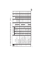
9 - 231391 - 221301 - 211241 558 E309 / 18 + 24 Buttonholes similar to handworked quality in outerwear E213 / 10 - 38 E328 / 16 - 20 E312 / 12 - 34 E2107 / 20 E311 / * 6 - 34 * The construction set upper gimp guide 578 5101 must be ordered additionally . Fine, tightly woven materials (e.g. poplin) E334 / 10 - 38 E327 / 10 - 38 Garment leather Waistbands on jeans, graduated cloth clamps E312 / 10 - 38 Materials of variing quality and thickness Small buttonholes in elastic material (e.g.
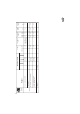
10 - 251301 - 241291 558 E512 / 10 - 50 E512 / 12 - 50 E2431 / L1 - L4 Loose, coarse weave cloth, plastic stitch formation Materials of variing quality and thickness E2417 / L1 - L3 E2407 / L1 - L3 Waistbands on jeans and similar Buttonholes in elastic material (e.g. knitware) Loose, coarse weave cloth Nähgut Buttonhole form V <--- before ---> N ---> N ---> N ---> N after Cutting Upper thread " " Upper thread, Under th., Gimp Short trimmer for 5,0 4,5 4,5 4,5 min.
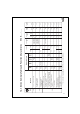
11 - 31391 - 21301 - 11241 558 E213 / 10 - 38 E328 / 16 - 20 E312 / 12 - 34 E107 / 20 E311 / * 6 - 34 * The construction set upper gimp guide 578 5101 must be ordered additionally . Fine, tightly woven materials (e.g. poplin) E334 / 10 - 38 E327 / 10 - 38 Garment leather Waistbands on jeans, graduated cloth clamps E312 / 10 - 38 E309 / 18 + 24 E212 / 10 - 38 E209 / 10 - 38 Materials of variing quality and thickness Small buttonholes in elastic material (e.g.
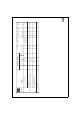
12 - 51301 - 41291 558 E512 / 10 - 50 E512 / 12 - 50 E431 / L1 - L4 Loose, coarse weave cloth, plastic stitch formation Materials of variing quality and thickness E417 / L1 - L3 E407 / L1 - L3 Waistbands on jeans and similar Buttonholes in elastic material (e.g. knitware) Loose, coarse weave cloth Nähgut Buttonhole form V <--- before ---> N ---> N ---> N ---> N after Cutting Upper thread " " Upper thread, Under th., Gimp Short trimmer for 5,0 4,5 4,5 4,5 min.
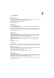
1.5 Optional Equipment 558 - 10012 Electromagnetically operated upper thread catcher The electromagnetically operated upper thread catcher immediately after the thread trimming procedure grips the upper thread. It holds this clamped and inserts it in the right seam during sewing of the next buttonhole. This means: • • • Secure seam beginning even with light, loose cloth. Beginning stitches pulled tight. Neating the underside of the buttonhole is unnecessary because the beginning thread is sewn over.
1 4 2 2 3 5 6 7 7 2 2 8 8 9 9 10 10 14
2. Operation 2.1 Removal and Placement of the Clamp Plates Caution Risk of Injury ! Pull the mains plug. Remove or place the clamp plates only with the machine turned off. The removal or placement of the clamp plates 3 and 5 occurs in the machine end position (see Chapter 2.3). The clamp operating lever 1 must be open ! This is the case when it is pushed to the back until it hits. ATTENTION ! In order to avoid damage to the needle the combined finger-eye protection 4 must remain swung down.
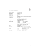
-221301 1 1 2 3 -211241 und -241291 1 1 2 3 16
Sub-classes -211241, -221301 and -241291: Removing the clamp plates – – – Swing the clamp plate holder 1 away to the side. Pull the spring mounted slide 3 in the direction of the arrow and remove the right clamp plate. Reach under the nail slit 2 and remove the left clamp plate. Placing the clamp plates – – – Place first the left, then the right clamp plate. The clamp operators 5 must reach into the forks of the clamp arms.
1 2 18
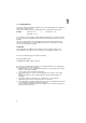
2.2 Turning On - Quick Stop - Restart Caution Risk of Injury ! Do not reach into the area of moving machine parts, particularly not under the knife and the cloth clamps. Turning on Turn on the drive motor with the hand shift lever 1. – Loosen the hand shift lever 1 out of its catch by pulling up on the ball head and bring into position "I". The catch prevents an unwanted turning on of the drive motor. Turning off Turn off the drive motor, as desired, with the hand shift lever 1 or the pedal 2.
1 2 3 4 5 6 20
Restart In order to avoid damage to the machine, when restarting after a quick stop it is essential to proceed as follows: – Lift the idle lever 5 until it jumps off of the nose 4 of the length setting slide 6. Attention ! This point is only to be carried out if the machine was turned off immediately after the first sewing stitches. – Pull the turn-off lever 1 forward. ATTENTION ! Before turning on the machine always bring the needle into the high position by catching in the handwheel 3.
1 22 2
2.3 End Position of the Sewing Machine – Turn handwheel 2 until it catches. The needle is in its highest position. ATTENTION ! Before turning the hand crank it is essential that the needle be brought into its high position by moving the handwheel into its catch. A bending of the needle or damage to the material is thus avoided.
2.
Needles Needle system: 558 Needle thickness: Nm 90 - 110 Dependent on type of sewing thread and material. Replacing the needle Caution Risk of Injury ! Pull the mains plug. Replace the needle only with the machine turned off. – Swing up the combined finger-eye protection. The needle is accessable without hinderance. – – Loosen screw 1 and remove the needle. – – Push the new needle as far as possible into the hole in the needle bar 2.
a b c e d c 26
2.5 Threading of the Underthread (Hook Thread) Caution Risk of Injury ! Pull the mains plug. Thread the underthread only with the machine turned off. The threading of the underthreads 1 (Page 28) is conducted as shown in the illustrations on pages 26 and 28 in alphabetical order of the letters: – Bring the machine in its end position (see Chapter 2.3). In the end position the hook bracket with the underthread tension must point to the front (to the seamstress).
-231391 -251301 -211241 -221301 -241291 m k l f i g h 1 2 p o n 28
Path of the underthread when using yarn or wool cones: If yarn or wool cones are used as hook thread then these are to be set on the as optional equipment available thread unreeler 1 (Order no. 558 3001) underneath the table. – – – Lead the thread through the thread guides under the table. Lead the thread up through the thread tube. The threading of the machine above the table is conducted as described above.
a 1 2 3 30
2.6 Threading the Gimp Caution Risk of Injury ! Pull the mains plug. Thread the lower and upper gimp only with the machine turned off. – Place tube and wire gimp rolls on the gimp roll holder 1. Place the gimp rolls with crosswinding vertically on the yarn plate 2 for an easy pull off of the gimp or thread. – For stiff and difficult to bend lower gimps choose the short feed over the as optional equipment available gimp roll holder 3 (Order no. 557 1103).
b d c 4 5 e f g 32
Sub-class -241291: This sub-class is equipped with gimp pulling device. Before the start of sewing it pulls the gimp back to the correct starting length. For correct positioning see the Service Instructions. – – – Remove the clamp plates (see Chapter 2.1). Turn the hand crank drehen until the hook bracket reaches the position shown. The gimp pulling device 1 faces forward (to the seamstress). Lead the gimp 2 from the lower gimp roll holder 4 through the side recess a in the machine housing.
a b c d f e 34
Upper gimp threading The feed of the upper gimp is possible with a gimp guider placed in front of the needle. The threading of the upper gimp is conducted as shown in the illustrations alongside in the alphabetical order of the letters: – – – Thread the gimp from the gimp roll holder a through gimp guide b. Lead the gimp through the gimp guide angle c and between the tension discs of the gimp pre-tensioning d. Thread the gimp through the gimp guide e and the gimp guider f.
a b d i e 36 h c 1 f g 2
2.7 Threading of the Upper Thread (Needle Thread) Caution Risk of Injury ! Pull the mains plug. Thread the upper thread only with the machine turned off. The threading of the upper thread is conducted as shown in the illustrations on pages 36 and 38 in the alphabetical order of the letters: – Bring the machine into its end position (see Chapter 2.3). In the end position the hook bracket with the underthread tension must face forward (to the seamstress).
k l 38
Threading by difficult to unreel thread rolls To achieve an easy pull off of the upper and underthread from the thread plate: – – Additionally guide the underthread through the holes 1 and 2.
1 2 5 40 3 4 6 7
2.8 Thread Tension Upper thread tension The upper thread tension on the machine arm must generally be set tighter than the underthread tension. It is set by turning the knurled nut 6. Tension increase Tension decrease = = turn to the right turn to the left The upper thread tension is executed as a dual tension: – Remaining rest tension 1 It serves to tauten the upper thread during the cutting procedure under the needle plate as well as to achieve the desired length of upper thread end.
1 4 2 5 6 3 42
Underthread tension The underthread tension is set by turning the knurled nut 3 on the hook bracket. Tension increase Tension decrease = = turn to the right turn to the left Thread pull-on spring for the underthread The thread pull-on spring 1 influences the pull-on of the underthread through its stopper width and pre-tension and thus the form and beading of the buttonhole. Setting the stopper width: Setting the pre-tension: Loosen screw 5 and turn the angle 4. Loosen screw 6 and turn angle 2.
1 2 44 3
2.9 Sewing – Place a work piece under the clamps and align precisely. The alignment can be made with markings or the stops available as optional equipment (see Chapter 1.5). Caution Risk of Injury ! Keep hands out from under the lowering cloth clamps ! – Pull the clamp operating lever 1 to the front until it touches. The work piece is fixed by the clamps. – Turn on the motor with hand shift lever 3.
1 2 3 4 5 46 6
Caution Risk of Injury ! As long as the seamstress is not yet familiar with the operation of the machine she should turn off the motor with the hand shift lever 3 or the pedal after sewing each buttonhole. Work procedure for the experienced seamstress After a suitable learning period the closing of the clamp operating lever 1 and the turning on and off of the motor with every buttonhole through the seamstress can be eliminated.
1 2 3 4 48
2.11 Buttonhole length Caution Risk of Injury ! Pull the mains plug. Set the buttonhole length only with the machine turned off. ATTENTION ! The changing of the buttonhole length requires a simultaneous change of the cutting length and thus the mounting of a different cutting block (see Chapter 2.12) ! Buttonholes without Taper Bar By buttonholes without taper bar the buttonhole length is determined through the position of the length setting slide 3: – – – – Loosen clamp screw 4.
1 Example: E407/L2 resp.
Buttonholes with Taper Bar By buttonholes with taper bar the different buttonhole lengths are achieved through insertion of the appropriate lower disc cam 1. It determines taper bar form and length. For exchanging the lower disc cam see Chapter 2.18. The order numbers for the different lower disc cams can be found on the device sheets for the 558 and 578.
1 2 3 4 5 6 7 8 52
2.12 Cutting Length The cutting length is determined by the length of the cutting block. It can be altered by changing the cutting block. The order numbers for the different cutting blocks are, taking into account the sewing device used (E no.), to be found on the device sheets for the 558 or 578. Changing the cutting block Caution Risk of Injury ! Pull the mains plug. Change the cutting block and cutting knife only with the machine turned off.
1 2 2 1 3 4 54
Mounting the cutting block at the top or bottom ? The mounting of the cutting block 2 and the cutting knife 1 is dependent on the sub-class with its sewing device (E no.) for cutting "before" or "after sewing": A. Sewing device for "cutting before sewing": – – Cutting block at bottom and cutting knife at top The material is supported by the cutting block during the cutting procedure.
1 56 2 3
2.13 Cutting Blocks Caution Risk of Injury ! Pull the mains plug. Remove the cutting block only with the machine turned off. A trueing (filing) of the cutting block becomes necessary, – – when the cutting block has been too strongly cut into by the cutting knife. when two different cutting knife forms have worked on the cutting block (Illus. 2).
2.14 Cutting Pressure 1 The cutting pressure is set with screw 1: Increase cutting pressure = Decrease cutting pressure = turn to the right turn to the left After each adjustment of screw 1 the cutting pressure must be checked. Checking the cutting pressure – Turn the machine with the hand crank.
2.15 Spreading of the Material 1 3 2 4 Caution Risk of Injury ! Pull the mains plug. Set the spreading only with the machine turned off. At the setting "cutting after sewing" the clamp plates are drawn apart after the run start of the material support plate. The material is drawn taut. At the setting "cutting before sewing" the clamp plates are drawn apart only after the cutting. The buttonhole slit is opened a little.
A B 1 2 A 3 B 60 4
2.16 Stitch Density Caution Risk of Injury ! Pull the mains plug. Set the stitch density only with the machine turned off. For the whole buttonhole length The stitch density is adjustable between 0.9 and 2 mm. It is determined by the required strength and the appearance of the buttonhole, as well as the thread size used. – – – Loosen screw 2. Move the transport lever 1. Movement in direction A Movement in direction B = = stitches become denser stitche are farther apart Tighten screw 2 again.
1 B 2 A 3 Seam width Cutting area Buttonhole width 62
2.17 Seam Width (Buttonhole Width) Caution Risk of Injury ! Pull the mains plug. Set the seam width only with the machine turned off. At the setting "cutting after sewing" the buttonhole width is arrived at as follows: Buttonhole width = Cutting area + 2 x seam width Setting the seam width – – – Loosen the wing nut 2. Move the connecting rod 3. Movement in direction A Movement in direction B = = wider seam narrower seam Tighten the wing nut 2 again.
1 2 3 4 64
2.18 Buttonhole Form The buttonhole form is determined by the two exchangeable disc cams 1 and 2: – – The upper disc cam 1 determines the eye form. The lower disc cam 2 determines, by taper bar buttonholes, the taper bar form and buttonhole length. Disc cams, cutting blocks and cutting knife for the different buttonhole forms and buttonhole lengths are to be found in the device sheet for the 558 and 578. Exchanging the disc cams – Bring the machine into the end position (see Chapter 2.3).
1 2 66
2.19 Change-over to Cutting Before or After Sewing Caution Risk of Injury ! Pull the mains plug. Conduct the change-over to "cutting before" or "cutting after sewing" only with the machine turned off vornehmen. The change-over from "cutting before" to "cutting after sewing" is only possible with sub-classes with the appropriate sewing device (E no.) (see Device Table in Chapter 1.4).
1 2 3 4 5 6 68
2. Timing of the closing and opening of the clamps – – – – Tilt the machine head up. Loosen screw 2. Push the clamp closing lever 1 in the appropriate arrow direction up to the stop. Tighten screw 2 again. 3. With or without cutting room between the seam rows – – – Loosen screws 5. Slide the lever 4 in the appropriate arrow direction up or down up to the stop. Attention ! The amount that the lever has to be moved is very small. Tighten screws 5 again. 4.
3. Maintenance 1 Caution Risk of Injury ! Pull the mains plug. Maintain the machine only when it is turned off. 3.1 Cleaning A clean machine protects against malfunctions ! Daily cleaning: Clean the area under the clamp plates, particularly around the hook bracket 1, of sewing dust, thread rests and cutting refuse. ATTENTION ! It is to be avoided that cutting refuse enters into the housing of the main disc cam at the back. If a vacuum is available this is recommended.
3.2 Lubrication 1 2 For lubrication of the machine only ESSO SP-NK 10 lubricating oil is to be used. SP-NK 10 is available at the DÜRKOPP ADLER AG sales offices. Check the oil level in the oil reservoirs – The lubrication of all moving parts the machine on the machine arm and hook bracket is through a central oil wick lubrication out of the oil reservoirs 1 and 2. If necessary fill oil through the filling plug up to the "max." marking.
3.
* * * * * * * * * * * * * 73
* * * * * * * 74
* * 75
4. Malfunction Remedies Malfunction Remedy 1. Machine does not start or runs unevenly. a) V-belt from the motor to the high-speed wheel or to the handwheel is too loose. Tension V-belt as per Installation Instructions for the 558. b) Machine is in front of the cutting position at the time of starting. With the main witch turned off and the needle high bring the machine into its end position with the hand crank. Reduce cutting pressure as per Chapter 2.14. 2.
Malfunction Remedy 5. Unequal stitch lengths or stitch positions. a) V-belt is too loose. Tension V-belt as per Installation Instructions for the 558. b) Gimp is too taut, jams or does not pass easily through the gimp hole of the needle plate . Use thinner gimp or insert a needle plate with larger gimp hole. For stiff and inflexible gimps use gimp roller holder on the table (Order no. 557 1103). 6. Missing stitches a) Needle is blunt, bent or not correctly inserted.
Malfunction Remedy 9. Needle breakage. a) Needle thickness is unsuitable for the material or the thread. Use a needle thickness as per Chapter 2.6 or as per sewing device (E no.). b) Needle is hitting the cloth clamps. The max. buttonhole width listed in the table on page 8 for each sewing device (E no.) may not be exceeded. Resetting by service personnel as per Service Instructions for the 558. 10. No clean seam beginning or unthreading of the upper thread.
5. Optional Equipment Electromagnetically Operated Upper Thread Catcher 5.1 General The sub-class 558-221301 has the the electro-magnetically operated upper thread catcher as standard equipment. All other sub-classes can, on request, be outfitted with it at the factory or have it retrofitted. Function The electromagnetically operated upper thread catcher grabs the upper thread immediately after the thread cutting procedure and hold it clamped. When sewing the next buttonhole it places it in the right seam.
b3 1 2 3 4 5 80
5.2 Electrical Connection ATTENTION All work on the electrical components of the upper thread catcher may only be conducted by electricians or appropriately trained personnel. The mains plug must be pulled. The transformer in the controls of the upper thread catchers is equipped with connections for following mains voltages: 1 ~ 200 V 1 ~ 220 V 1 ~ 380 V 1 ~ 415 V At the factory the transformer is connected to 1 ~ 380 V.
6 b2 7 8 82
– The cam 6 connected with the length setting slide operates the switch b2. The thread catcher lowers. Through the slide of the opener lever 8 onto the opener 7 the thread catcher is opened. Via the curve plate 3 it is swung in front of the needle to grip the upper thread. – During further lowering the opener lever 8 falls off the opener 7. The thread catcher closes. – After cam 6 has run over the switch b2 the thread catcher with the clamped thread moves back into the upper position.
1 b4 b1 84 b5
5.4 Turn-on Interlocks Switch b4 With the cloth clamps opened the machine can only be turned on in its end position. For this cams 1 operates the switch b4. Switch b1 In all other machine positions with the cloth clamps opened a turning on and thus also the thread catcher function are blocked by switch b1. The safety switch b1 is bypassed by the activated switch b4. The machine, with opened cloth clamps, can only be started in its end position.
3 1 4 2 5 11 6 12 7 13 8 14 9 15 10 86
5.5 Setting Caution Risk of Injury ! Pull the mains plug. Make setting only with the machine turned off. 5.5.1 Lift of the Electromagnet The lift of the electromagnet should be 20 mm. Measured is the distance between the upper edge of the protective sleeve 4 and the upper edge of the anchor 3 in both positions (ON and OFF). The difference must be 20 mm. – – – Loosen lock nut 6. Screw anchor 3 further in or out. Tighten lock nut 6 again. 5.5.
2 3 1 4 7 88 5 6 8 9
5.5.3 Lowering Movement Opener setting After the closing of the thread gripper 1 the opener lever 3 must move past behind the opener 2 unhindered. Thread gripper 1 must thereby remain closed. – – Check the unhindered movement of the opener lever 1. If necessary, set opener 2 accordingly with screw 9. Insertion position When sewing the right buttonhole seam and simultaneous manual operation of the magnet the inserted upper thread end should be overcast.
1 2 4 5 3 6 7 8 90 9
5.5.4 Gripping Movement Bringing the thread gripper in gripping position After sewing the left buttonhole seam the thread gripper 3 must be set in the precise gripping position for the upper thread. – Turn the handwheel until the sewing sequence for the left buttonhole seam is completed and the handwheel catches. – Turn the material support plate with the hand crank about 14 mm farther. For this measure the distance between bearing block 2 and machine arm 1. If the measured distance is e.g. 21.
5.5.5 Switches for the Upper Thread Catcher Controls b1 1 b4 ATTENTION ! Before commissioning the machine all switches must be set as described below. Switch b4 Safety switch b1 is bypassed by the operation of switch b4. The machine, with open cloth clamps, can only be started in its end position. In the end position the switching piece 1 must turn on the switch b4 and hold it operative. – Bring the machine in its end position (see chapter 2.3).
1 b3 2 3 4 5 Switch b3 After the sewing in of the upper thread end in the right buttonhole seam switch b3 determines the timing of the raising of the thread catcher. The upper thread end should be held as long as possible. Thereby the switching roller 2 must have fallen from the switching piece 3 before the clamping piece 4 of the thread catcher can run onto the clamp shackle 5. This corresponds to a machine position shortly before entering in the buttonhole eye. – – – Loosen screws 1.
b1 b2 1 2 Switch b2 After the trimming of the upper thread switch b2 operated by cam 1 determines the timing for lowering the thread catcher. Cam 1 is connected to the length setting slide. With the setting of a different buttonhole length the correct switch timing is thus set automatically. – Just before ending the left buttonhole seam turn the handwheel until it catches. The sewing drive turns off. – Turn the material support plate with the hand crank about 6 mm farther.
1 b1 Switch b1 Safety switch b1 is directly under the clamp frame 1. It is to prevent the machine being turned on with the cloth clamps open. – Switch b1 must, with open cloth clamps, be open. With the cloth clamps closed it must be closed. – Align switch b1 to the clamp frame 1 so that the above mentioned switching functions are assured during the whole advancing movement of the material support plate (with material in place).
10 b3 7 b5 3 b2 b1 1 13 2 b10 5 4 11 96 L1 12 6 b4
5.6 Attachment Caution Risk of Injury ! Pull the mains plug. The attachment of the upper thread catcher may only be conducted with the machine turned off and only by trained skilled personnel. 5.6.1 Pre-assembling the Wiring Distributor The designation numbers affixed to the cables and position numbers in these instructions are indentical with the cable numbers in the enclosed hook-up diagram 558 10296 and in the circuit diagram 558 10295. – – – – – Lay the cables 2 and 3 through the holder tube 12.
10 b3 7 b5 3 b2 b1 1 13 2 b10 5 4 11 19 20 L1 12 6 11 13 14 15 16 17 98 b4
5.6.2 Laying the Wiring 12 21 20 – – – – – – – – – – – Pull the hand crank 17 from the shaft end. Loosen nut 16 ( ATTENTION: lefthand thread) Loosen nut 13. Pull off the high-speed wheel 15 with the drive bush 14. Attach the holder tube 11 with cables 1, 4 and 7 to the cover plate. Reattach the high-speed wheel 15 again and tighten nuts 13 and 16. Set a clearance of 1 mm between the latches (see Service Instructions 558). Replace hand crank 17 again and let catch.
b1 21 22 – – – – – 100 b2 23 b4 6 Fasten angle 21 with switches b1 and b2 to the support 22. Attach the cable clips. Mount switch b4 to the outside of the control curve housing. Secure the cable 6 with a clamp. Mount operator 23 for switch b4 centered in its slot under the material support plate.
5.6.3 Control Unit 1 2 – – – Mount the control unit 2 under the table. Lay the cable 1 from the wiring distributor to the control unit 2 (plug b10) and aatch to the table with a clamp. The laying of the cable must be conducted with the machine head tilted up. Connect the mains lead and connector lead to the motor as per the hook-up diagram. ATTENTION After connecting the sewing procfedure may only be turned on if all setting have previously been made according to Chapter 5.5.
5.6.4 Mounting Switch b3 b3 1 2 In the parts set there are 2 switching cams for the different sub-classes: Sub-class Switching cam -221301 , -251301 -231391 , -241291 -211241 straight switching cam milled switching cam milled switching cam The milling must be deepened – – – – – 102 Loosen and remove cover plate 2. Mount the appropriate switching cam 1 to the machine plate. Mount switch b3 with angle 3 to the cover plate 2. Reattach cover plate 2. Set switch b3 (see chapter 5.3.5).
5.6.5 Mounting the Switching Rail for Switch b2 1 2 3 4 2 – – – – – – Loosen screw 4. Remove the block 2 from the length setting slide. Screw on the switching rail 1 with the extension to the block 2 Tighten screw 3. Reattach the complete switching rail with block 2 again. Tighten screw 4.
5.6.6 Mounting the Upper Thread Catcher on the Machine Arm 1 2 3 b5 4 5 6 7 8 s1 9 – – Remove the head cover 8. – – Reattach head cover 8 again. – – Fasten stopper angle 11 to the toothed segment. – – – Mount switch b5 on holder 4. 104 10 11 12 Replace the protecting bar 10 for the upper toothed segment with the at the right side shortened protecting bar found in the parts set. Fasten the mounting angle 2 for the thread catcher with screws 1 and 3 to the machine arm.