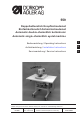
559 Doppelkettenstich Knopflochautomat Einfachkettenstich Schnürlochautomat Automatic double-chainstitch buttonholer Automatic single-chainstitch eyelet machine Bedienanleitung / Operating Instructions Aufstellanleitung / Installation Instructions 2 Serviceanleitung / Service Instructions 3 Postfach 17 03 51, D-33703 Bielefeld Potsdamer Straße 190, D-33719 Bielefeld Telefon +49 (0) 5 21/ 9 25-00 Telefax +49 (0) 5 21/ 9 25 24 35 www.duerkopp-adler.
Anleitung, komplett / Manual, complete 559 Übersicht Summary Bedienanleitung Aufstellanleitung Serviceanleitung Operating Instructions Installation Instructions Service Instructions Bauschaltplan Interconnection-diagram 9890 580001 B 9890 580001 B Pneumatikgeräteplan Pneumatic circuit plan 9770 559001 9770 559001 Alle Rechte vorbehalten. Eigentum der Dürkopp Adler AG und urheberrechtlich geschützt.
Foreword This instruction manual is intended to help the user to become familiar with the machine and take advantage of its application possibilities in accordance with the recommendations. The instruction manual contains important information on how to operate the machine securely, properly and economically. Observation of the instructions eliminates danger, reduces costs for repair and down-times, and increases the reliability and life of the machine.
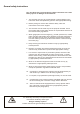
General safety instructions The non-observance of the following safety instructions can cause bodily injuries or damages to the machine. 1. The machine must only be commissioned in full knowledge of the instruction book and operated by persons with appropriate training. 2. Before putting into service also read the safety rules and instructions of the motor supplier. 3. The machine must be used only for the purpose intended. Use of the machine without the safety devices is not permitted.
Index Page: Part 2: Installation Instructions cl. 559 1. Scope of delivery . . . . . . . . . . . . . . . . . . . . . . . . . . . . . . . . . . . . . . . . . . . . . . . . . 3 2. General notes and securing devices . . . . . . . . . . . . . . . . . . . . . . . . . . . . . . . . . . . . . 3 3. Table plate with dimensioning . . . . . . . . . . . . . . . . . . . . . . . . . . . . . . . . . . . . . . . . 4 4. Lifting eye bolt. . . . . . . . . . . . . . . . . . . . . . . . . . . . . . . . . . . . . . . .
4 1 3 6 2 5
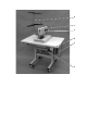
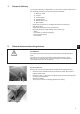
1. Scope of delivery The scope of delivery is dependent on your order. Please check before the assembly whether all required parts are available. – 1 Machine head – 2 Control – 3 Control panel – 4 Thread stand – 5 Maintenance unit – 6 Main switch – Right and left spacer for the distance between buttonhole and fabric edge – Tools and small parts in the accessories – Optional equipment (depending on the order) e.g.: - Stand - Pneumatic connection package - Integral sewing lamp - Foot switch 2.
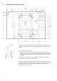
3. Table top with dimensioning If you manufacture the table top yourself, take the above sketch as an example for the dimensioning. The table top should be approx. 40 mm thick. Hole for the thread stand Positions for screwing on the brackets. To fasten the machine safely, use only the screwed inserts M8 x 25 DIN 7965 (the screwed inserts are not included in the accessories) with the screws for the brackets.
4. Lifting eye bolt The lifting eye bolt helps you to lift the automat into the stand. For example you can hoist the automat by a ceiling crane or you put a rigid bar (e.g. the bar of the thread stand) through the lifting eye bolt and lift the automat with 2 persons. The lifting eye bolt is included in the accessories. – Screw the lifting eye bolt 8 on the automat. – Lift the automat into the stand. – Unscrew the lifting eye bolt 8 when the automat is mounted. 5.
6. Assembly of the control Attention! The control must not stand on the floor because otherwise the ventilation grid are covered. This can lead to the overheating of the control. 8 2 1 7 3 9 4 – – – – 6 8 10 5 Screw the control on the underside of the table top with the screws 2 and 3. The side carrying the data plate points to the front. Connect all plugs in field 1 and 4 with the respective bushes.
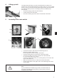
7. Potential equalization 3 4 1 2 6 5 2 – – – Connect the potential compensation cable 1 to the stand using the screw and toothed washer 2 (included in the accessories). Screw on the potential compensation cable 1 from the stand together with the potential compensation cable 3 from the automat, on the control box through the screw 4. Screw on the potential compensation cable 5 from the sewing motor to the control box through screw 6.
8. Assembly of the waste container 1 2 3 1 – – – 8 Screw the waste container under the pedestal of the automat as shown in the illustration. Connect the hose 3 with the waste container and the hose nozzle 2. The hose 3 sucks cutting waste into the container. Connect the waste container and the pressure supply with the compressed-air hose 1 (in the accessories).
9. Installation of the automatic buttonholer 1 2 3 9.1 Adjusting the working height The working height is infinitely variable between 73 cm and 90 cm (measured up to the upper edge of the table top). – Loosen the locking screws 1 and 2 on both sides of the stand. – Set the working table of the automatic buttonholer to the desired working height. – Tighten the locking screws 1 and 2. 9.
9.3 Connecting the pedal 1 2 – – – – – 9.4 Place the pedal 1 under the stand. Screw off the handwheel and the belt protection of the automat. Guide the cable of pedal 1 through the cable duct of the automat to the top. Connect the cable of pedal 1 with bush 2 (X406). Screw the belt protection and the handwheel on again. Securing the pedal 1 2 – – 10 Screw the two support plates down with nut 1 until the automat stands firmly and safely. Screw the counternut 2 upwards and tighten it.
9.5 Connecting the maintenance unit 1 4 2 3 The pneumatic system of the machine and its optional equipment must be supplied with compressed air containing absolutely no water or oil. – Screw the maintenance unit on the stand. – Connect the maintenance unit with the thicker one 3 of the three compressed-air hoses coming out of the cable chute of the automat. – Connect the thinner hose to the connection 4. – Connect the maintenance unit with your pressure supply.
10. 4 Lubrication 5 1 1 3 1 1 1 2 1 2 Caution: Danger of injury ! Oil can cause skin eruption. Avoid a longer contact with the skin! Wash yourself thoroughly after a contact! ATTENTION ! The handling and disposal of mineral oils is subject to legal regulations. Deliver used oil to an authorized collecting station. Protect the environment.
10.1 Fill the oil reservoirs – Fill up the reservoirs 2 and 4 through the feed openings 1 and 3 up to the marking “max”.
11. Installing the sewing software 11.1 General Loading a specific sewing software in the DACIII control unit is possible with the help of the “Programmed Dongle”. The “Programmed Dongle” has a label indicating the class and software version. Such a loading (booting) may be used in order to provide several DACIII control unit with a sewing software (first installation) or to install a newer machine software (update).
11.3 Setting the sewing equipment After the loading of the program, the control panel will display an error message “9010" (enter the sewing equipment). “OK” Key ïðñò Keys Press the “OK” key. Enter the code “2548” using the arrow keys. “OK” Key Press the “OK” key. The menu item 511 (sewing equipment) will be activated. “OK” Key ñò Keys Press the “OK” key. Select the equipment matching to the machine and subclass using the arrow keys and confirm it through the “OK” key.
12. Sewing test After finishing the assembly work a sewing test has to be made: – Insert the mains plug. Caution: Danger of injury ! Needle thread, looper thread and gimp thread must only be threaded in when the machine is switched off or in the threading in mode! – – – – – – – – – Insert needle Thread in looper thread (see operating instructions). Thread in needle thread (see operating instructions). If desired, thread in gimp thread (see operating instructions). Switch on main switch.