559 Doppelkettenstich Knopflochautomat Einfachkettenstich Schnürlochautomat Automatic double-chainstitch buttonholer Automatic single-chainstitch eyelet machine Bedienanleitung / Operating Instructions Aufstellanleitung / Installation Instructions 2 Serviceanleitung / Service Instructions 3 Postfach 17 03 51, D-33703 Bielefeld Potsdamer Straße 190, D-33719 Bielefeld Telefon +49 (0) 5 21/ 9 25-00 Telefax +49 (0) 5 21/ 9 25 24 35 www.duerkopp-adler.
Anleitung, komplett / Manual, complete 559 Übersicht Summary Bedienanleitung Aufstellanleitung Serviceanleitung Operating Instructions Installation Instructions Service Instructions Bauschaltplan Interconnection-diagram 9890 580001 B 9890 580001 B Pneumatikgeräteplan Pneumatic circuit plan 9770 559001 9770 559001 Alle Rechte vorbehalten. Eigentum der Dürkopp Adler AG und urheberrechtlich geschützt.
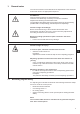
Foreword This instruction manual is intended to help the user to become familiar with the machine and take advantage of its application possibilities in accordance with the recommendations. The instruction manual contains important information on how to operate the machine securely, properly and economically. Observation of the instructions eliminates danger, reduces costs for repair and down-times, and increases the reliability and life of the machine.
General safety instructions The non-observance of the following safety instructions can cause bodily injuries or damages to the machine. 1. The machine must only be commissioned in full knowledge of the instruction book and operated by persons with appropriate training. 2. Before putting into service also read the safety rules and instructions of the motor supplier. 3. The machine must be used only for the purpose intended. Use of the machine without the safety devices is not permitted.
Index Page: Part 3: Service Instructions Class 559 1. 1.1 General notes Necessary program setting . . . . . . . . . . . . . . . . . . . . . . . . . . . . . . . . . . . . . . . . 3 2. 2.1 2.2 2.3 2.4 Adjusting the locking positions General notes . . . . . . . . . . . . Looper and spreader eccentric . . Rotary thread take-up disc . . . . Throw eccentric . . . . . . . . . . . . . . . 4 5 6 7 3. Needle bar positioning . . . . . . . . . . . . . . . . . . . . . . . . . . . . . . . . . . . . . . . . . .
Index Page: 11. Looper height . . . . . . . . . . . . . . . . . . . . . . . . . . . . . . . . . . . . . . . . . . . . . . . . 35 12. Adjusting the looping stroke . . . . . . . . . . . . . . . . . . . . . . . . . . . . . . . . . . . . . . 36 13. Needle bar height. . . . . . . . . . . . . . . . . . . . . . . . . . . . . . . . . . . . . . . . . . . . . . 38 14. Distance between looper and needle . . . . . . . . . . . . . . . . . . . . . . . . . . . . . . . . . 39 15. Needle guard . . . . . . . .
1. General notes The service manual on hand describes the adjustment of the automatic buttonholer 559 in an appropriate sequence. ATTENTION ! Various setting positions are interdependent. Therefore it is absolutely necessary to make the individual adjustments following the described order.
2. 2.1 Adjusting the locking positions General notes 3 With the help of the locking positions an easy adjustment of the needle motion to the looper and spreader motions is possible. When the arm shaft is in staking-out position, the rotary thread take-up disc and the eccentrics for the spreaders, the loopers and the connecting stitch have to be in staking-out position, too. The positions have been set by the manufacturer in such a way that standard material can be sewn with the 559.
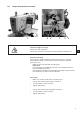
2.2 Looper and spreader eccentric 6 1 4 3 2 5 Caution: Danger of injury! Switch the main switch off. Adjust the eccentrics only with the sewing machine switched off. 3 Standard checking When the arm shaft is staked out with arresting pin 1, it should be possible to stake out the looper eccentric 3 and the spreader eccentric 4, too. – Stake out the arm shaft with arresting pin 1. Important ! In this position the needle bar must be in the top dead center in front of the left entry point.
2.3 Rotary Thread Take-up Disc 2 1 Caution: Danger of injury! Switch the main switch off. Adjust the rotary thread take-up disc only with the sewing machine switched off.
2.4 Throw eccentric 4 3 2 1 5 Caution: Danger of injury ! Switch the main switch off. Adjust the rotary thread take-up disc only with the machine switched off. 3 Standard checking When the looper turret 5 is in its right end position (right entry point), the arresting pin 4 inserted in the eccentric 2 should abut in the notching 1 at the arm. – Turn the arm shaft in such a way that the looper turret is on the right side (right entry point).
3. Needle bar positioning 3 2 1 4 2 Caution: Danger of injury! Exercise utmost caution when making adjustments with the machine running. Standard checking When the machine positions automatically after being switched on, the needle bar must be in the top dead center. The looper turret is in its right end position (right entry point) then. – Switch the machine on. The machine positions automatically.
4. Aligning the looper turret 2 1 3 Caution: Danger of injury! Switch the main switch off. Align the looper turret only with the machine switched off. 3 Note Please observe the necessary program setting as described in chapter 1.1. Standard checking When the machine has reached its initial position after switching on the main switch, it must be possible to stake out the looper turret 2 with the arresting pin 1. – Switch the machine on.
5 6 5 8 7 9 10 10
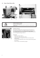
5. Aligning the needle bar parallel to the looper turret Caution: Danger of injury! Switch the main switch off. Adjust the needle bar only with the main switch switched off. Standard checking The needle bar 1 and the looper turret 3 must be in parallel position. – Remove the cutting block. – Unscrew the finger protection and the head cover. Note ! Do not separate the cable from the head cover. – Switch the machine on. The machine runs to its initial position. – Switch the machine off.
X2 1 4 12 1 X1 3 2
6. Transversal motion of the fabric support plate Caution: Danger of injury! Exercise utmost caution when making adjustments with the machine running. Note Please observe the necessary program setting as described in chapter 1.1. Standard checking The looper turret 3 must be in the center of the fabric support plate 4. When the automatic buttonholer is in reference position, the dimensions X1 and X2 must be equal when the fabric support plate is adjusted correctly.
7 6 8 5 Correction – Switch the machine on and press the keys “P” and “ß” on the control panel simultaneously. – Enter code “2548”. – Press key ”OK”. The control switches to the technician level. – Select the menu “603” with the key “+”. In this mode the step motors are dead. – Switch the menu on with key ”OK”. Caution: Danger of injury! Exercise utmost caution when making adjustments with the machine running.
7. Longitudinal motion of the fabric support plate 3 2 1 1 Caution: Danger of injury! Exercise utmost caution when making adjustments with the machine running. 3 Note Please observe the necessary program setting as described in chapter 1.1. Standard checking When the machine is in reference position, the distance between the edge 3 of the fabric support plate 2 and the front edge 1 of the throat plate support should amount to approx. 113 mm.
5 4 6 Correction – Switch the machine on and press the keys “P” and “ß” on the control panel simultaneously. – Enter code “2548”. – Press key ”OK”. The control switches to the technician level. – Select the menu “603”with the key “+”. In this mode the step motors are dead. – Switch the menu on with key ”OK”. Caution: Danger of injury! Exercise utmost caution when making adjustments with the machine running. – – – – – – Shift the fabric support plate manually to the desired measurement.
8. 8.1 Clamping plates Inserted clamping plates ô= 0 4 3 2 1 Caution: Danger of injury! Switch the main switch off. Adjust the clamping plates only with the machine switched off. 3 Standard checking The inserted clamping plates 1 and 2 should be in the holding groove 4 of the fabric support plate in parallel position and without clearance. Inserting and removing must, however, be fingertip easy. – Insert both clamping plates and check whether there is as little clearance as possible.
8.2 Aligning the clamping plates X2 X1 3 2 1 4 Caution: Danger of injury! Switch the main switch off. Adjust the clamping plates only with the machine switched off. Standard checking Both clamping plates 3 must be adjusted in such a way that the distance between clamping plate and fabric support plate 1 is equal everywhere (distance X1 = distance X2). – Put on the right clamping plate. – Check distance X1 and X2. Correction – Insert the right clamping plate.
8.3 Adjusting the spreading 2 X 1 4 Caution: Danger of injury! Exercise utmost caution when making adjustments with the machine running. 3 Standard checking The distance X between the clamping plates 2 and the fabric support plate 1 should amount to 1.3 mm (non-spreaded) and to 0.3 mm (spreaded). – Insert the clamping plates 2 and switch the machine on. – Press the keys “P” and “F” on the control panel simultaneously. – Enter code “2548”. – Press key ”OK”.
X 6 5 8 7 Correction clamping plate – Switch the machine on. – Press the keys “P” and “F” on the control panel simultaneously. – Enter code “2548”. – Press key ”OK”. The control switches to the technician level. – Select the menu “601” with the key “+”. – Switch the menu on with key ”OK”. – Select the function “Y03” (closing the fabric clamp). – – Press the key ”OK”. The fabric clamps close. Loosen the screws 6. Set the distance X to 1.3 mm (basic adjustment) with the hexagonal spanner 5.
8.4 Height of the fabric clamps 3 2 Ø 12 mm 3 2 1 Caution: Danger of injury! Switch the main switch off. Adjust the fabric clamp height only with the machine switched off. 3 Standard checking The distance between the open fabric clamps 2 and 3 should amount to 12 mm. – Remove the clamping plates. – Open the clamping plate and test e.g. with a twist drill Ø 12 mm whether the fabric clamps 2 and 3 have the required distance. Correction – Adjust the distance with core pin 1.
8.5 Adjusting the locking sheet 2 1 3 Caution: Danger of injury! Switch the main switch off. Adjust the locking sheets only with the machine switched off. Standard checking The locking sheets 1 must be adjusted in such a way that the stops 3 of the clamping plates abut centrally and as tight as possible. – Insert the clamping plates. – Check the position of the locking sheet 1 to the stop 3. Correction – Adjust the locking sheet 1 with the special spanner 2 (in the accessories).
8.6 Arrest of the clamping plates 2 1 4 3 Caution: Danger of injury! Exercise utmost caution when making adjustments with the machine running. 3 Standard checking There must be a minimum clearance in the height of the inserted clamping plates 2 when: · · – – – – – – no material is loaded approx. 8 mm thick material is loaded and the clamps are closed. Insert the clamping plates. Switch the machine on. Close the fabric clamps.
8.7 Adjusting the fabric clamping pressure 2 1 2 4 3 Caution: Danger of injury! Switch the main switch off. Adjust the fabric clamping pressure only with the machine switched off. Standard checking The clamping pressure should be adjusted in such a way that the sewing material is clamped safely and tightly. Please observe that the sewing material is not damaged by a too high pressure. The standard pressure amounts to 4 bar. Correction – Switch the machine off and tilt it up.
9. 9.1 Adjusting the seam width Presetting the seam width B 2 A 1 B A 3 Caution: Danger of injury! Switch the main switch off. Adjust the seam width only with the machine switched off. 3 Standard You can choose among two seam widths: · · Seam width “Narrow” = Lever 2 mounted in position B Seam width “Wide” = Lever 2 mounted in position A The seam width “Narrow” is 2.2 mm and “Wide” 3.3 mm.
Setting the sewing equipment – Press the keys “P” and “F” of the control panel simultaneously. – Enter code “2548”. – Press the “OK” key. The control switches to the technician level. – Select the menu “500" (configuration automatic buttonholer). – Press the “OK” key. – Select the menu “511" – – Press the “OK” key. Set the sewing equipment (the seam width will then be adjusted automatically to match the sewing equipment - see table).
Notes: 3 27
9.2 Needle zero position 2 1 4 3 Caution: Danger of injury! Switch the main switch off. Set the needle zero position only with the machine switched off. Standard checking The needle bar oscillates unidirectionally from the left (inside) to the right (outside). The needle zero position is on the left (inside). With the needle zero position the inner stitches of the forward and backward lip must be in a line. Note Please observe the necessary program setting as described in chapter 1.1.
10. Cutting knife (Eyelet knife) 10.1 Position of the cutting knife 1 2 Caution: Danger of injury ! Switch the main switch off. Adjust the cutting knife only with the machine switched off. 3 Standard checking In case of automates for “cutting after sewing” the cutting knife 2 should cut exactly between the seam rows and in the center of the eyelet (see illustration a).
The cutting knife has to be adjusted in such a way that it cuts in the center of the sewn buttonhole shape. – Insert the cutting block. – Insert a short needle. – Load a piece of paper or cardboard as sewing material. – Sew a buttonhole. – Check the position of the cut. Correction – Loosen two screws 5 at the base plate 3. – Correct the position of the cutting knife 2 laterally. – Tighten the screws 5 at the base plate 3. – Loosen screw 4. – Shift the cutting knife 2 to the front or to the back.
10.2 Adjusting the knife parallel to the cutting block 3 2 – – – 1 7 6 5 4 Loosen screws 1, 2 and 3. Put the key 4 (in the accessories) on the hexagonal bolt 5 and twist it. Push the cutting block 6 downward.
10.3 Cutting block adjustment 4 3 2 1 6 5 Caution: Danger of injury ! Switch the main switch off. Adjust the cutting block only with the machine switched off. The cutting length can be altered by changing the cutting block. The cutting length is determined by the cutting block length. Standard checking The cutting block 3 must be in parallel position to the cutting knife 4. The cutting block stop 5 has to be adjusted so that the knife mark on the cutting block 3 reaches the indicated cutting length.
10.4 Adjusting the switch for the trimming system 1 2 1 Caution: Danger of injury ! Switch the main switch off. Adjust the trimming system only with the machine switched off. 3 Standard checking Before the fabric support plate continues transporting the fabric, the cutting stamp must be in its upper position. In order to avoid a possible collision, switch 1 checks the position of the cutting stamp. Correcting the height of the switch – Loosen screw 2. – Adjust the height of switch 1 accordingly.
10.5 Cutting pressure Standard checking The cutting pressure is adjustable in order to keep the strain of all components as low as possible and to increase the durability of the cutting knife. According to the sewing material and the material thickness the cutting pressure should be adjusted as low as possible. However, it has to be adjusted in such a way that the material is safely cut. The cutting pressure is coordinated to the different cutting lengths in the program. Correction – See menu item 601. 10.
11. Looper height 8 7 2 6 3 4 1 5 Before adjusting the looping stroke as well as the needle bar height and particularly after needle breakage it is necessary to check the correct looper height. Use gauge 2 for checking the looper height. 3 Caution: Danger of injury ! Switch the main switch off. Adjust the height of the looper only with the machine switched off.
12. Adjusting the looping stroke 2 1 4 3 Caution: Danger of injury ! Switch the main switch off. Adjust the looping stroke only with the machine switched off. Standard checking The looping stroke is the way of the needle bar from its lowest position up to the point where the left or right looper tip is at the level of the middle of the needle. The looping stroke is 2.7 mm. – Turn the handwheel in rotation direction until the needle is in the bottom dead center.
6 4 3 5 Correction Shift the clamping rings 3 and 4 in such a way that both looper points have the same distance to the needle. Adjust the left looper 8 and the right looper 7 so that both looper points in looping stroke position have the same position (X) to the needle. That means both looper points must be at an equal distance either before or behind the needle. – Loosen the screws at the clamping rings 3 and 4. Adjust the looper position as described by shifting the clamping rings.
13. Needle bar height 2 1 5 4 3 Caution: Danger of injury ! Switch the main switch off. Adjust the needle bars only with the machine switched off. Standard checking The needle bar has to be adjusted in such a way that approx. ¾ of the needle’s eye 6 is to be seen under the left looper point when the needle bar has moved upward by 2.5 mm from the looping stroke position. – Turn the handwheel until the needle is in the bottom dead center.
14. Distance between looper and needle 3 2 4 1 Caution: Danger of injury ! Switch the main switch off. Adjust the needle protection only with the machine switched off. 3 Standard checking The looper points 1 and 4 should be in a distance of max. 0.1 mm to the needle 3. The distance between looper and needle should be equal during the whole rotary motion of the looper turret. – Turn the handwheel until the left looper point is at the level of the middle of the needle.
15. Needle guard 1 2 3 Caution: Danger of injury ! Switch the main switch off. Adjust the needle guard only with the machine switched off. Standard checking The needle 1 must slightly abut on the needle guard 2 until the looper point have reached the needle. The distance between looper and needle must amount to 0.1 mm. The needle guard has been adjusted by the manufacturer. In general, a readjustment is not required.
16. Spreader 6 5 4 3 2 1 8 7 Caution: Danger of injury ! Switch the main switch off. Adjust the spreader only with the machine switched off. Standard checking The distance between the fork spreader 5 and the left looper 4 must correspond to the thickness of the looper thread used (see illustration X opposite). The right spreader 2 should move as closely as possible on the top side of the right looper 3, but without touching it.
17. Spreader plate X2 X1 3 2 1 Caution: Danger of injury ! Switch the main switch off. Adjust the spreader plate only with the machine switched off. Standard checking The opening and closing of the spreaders is effected by the alternate motion of the spreader plate 2.
18. Throat plate 2 1 Caution: Danger of injury ! Switch the main switch off. Adjust the throat plate only with the machine switched off. 3 Standard checking The needle should penetrate the needle hole of the throat plate on one side at the edge 1. The throat plate has to be positioned as highly as possible. Thus it is avoided that the material is pressed down too much at the moment of the needle penetration.
19. Adjusting the needle thread knife 3 2 1 4 Caution: Danger of injury ! Switch the main switch off. Adjust the needle thread knife only with the machine switched off. Standard checking The cutting motion of the needle thread knife 2 is effected after sewing. The exact cutting moment is fixed in the control. When in final position the knife holder 3 must not touch the spreader stop 1.
8 7 6 5 12 11 10 9 Correction of the knife motion – Loosen the counter-nuts 5 and 8. – Adjust the stop screws 6 and 7 according to the rule. – Tighten the counter-nuts 5 and 8. 3 Adjusting the height of the knife – Loosen screw 10. – Adjust the height of the knife holder 9 correspondingly. Swing the knife holder 9 manually to check the free movement. – Tighten screw 10 again. Adjusting the distance to the needle – Loosen screw 11. – Shift knife 12. – Tighten screw 11.
20. Adjusting the fabric clamps 2 1 6 5 4 7 3 Caution: Danger of injury ! Switch the main switch off. Adjust the fabric clamps only with the machine switched off. Standard checking Between the needle 2 and the upper fabric clamp 1 there should be a distance of 1 mm over the whole length and in the eyelet. – Press key “P”. 3 – Select the menu “150”. – Enter “+ 0.5”. – Select the menu “162”. – – – – Set the cutting area to “0.7”. Insert the clamping plates. Insert a new needle.
21. Thread controller spring 1 5 4 3 2 Caution: Danger of injury ! Switch the main switch off. Adjust the thread controller spring only with the machine switched off. Standard checking The thread controller spring 1 must hold the looper thread tensioned until the needle with the needle thread has accurately penetrated the triangle formed by the spreader. – Insert and clamp the material.
22. Maintenance 1 6 3 2 Caution: Danger of injury ! Switch the main switch off. Maintenance work of the automatic buttonholer must only be carried out with the machine switched off. The daily or weekly maintenance work (cleaning and oiling) to be carried out by the operators of the automatic buttonholer is described in Part 1: Operating Instructions. This is only listed in the following table to complete the picture.
23. Annex 23.1 Adjusting operations without head cover 3 2 1 When the head cover is taken off, the machine is secured against unintentional starting. If you want to operate the machine without head cover for adjusting purposes, the plug 2 can be put on the connecting cable 3. The plug is in the switch casing 1. 3 Caution: Danger of injury ! Remove the head cover for adjustment work only. Exercise utmost caution when making adjustments with the machine running.
23.2 Fuses in the control box 1 2 The fuses 1 and 2 for the control are on the back of the control box. Only insert the fuses indicated in the circuit diagram. 23.3 Exchange of the control See: Part 2: Installation Instructions.
24. Service menu (technician level) In the service menu of the 559 various basic adjustments and test programs can be executed. 24.1 Activating the service menu – Press the keys “P” and “F” simultaneously on the control panel. A code query appears. – Enter the code “2548” with the cursor keys. – Press key “OK”. The menu item “500” (configuration of the automate) appears. 24.2 Selection of a menu item/submenu item – Select the desired menu item with the keys “ñ” or “ò”.
24.
24.6 Menu items 500 (Configuration automatic buttonholer) 24.6.1 Menu item 501 (Loading position) Via this menu item the desired loading position can be set. Input: 0 … 68 (mm) Standard: 68 The value entered corresponds to the distance from the cutting point. The value “0” corresponds to the cutting-open position. The standard value is identical with the seam beginning position. – Quit the menu item with key “ESC”. 24.6.
24.6.5 Menu item 511 (Sewing equipment) Various sewing equipment can be used with the automatic buttonholer 559. The selected sewing equipment is entered via this menu item. Input: 1501, 1502, 1504, 1521, 1522, 1524, 1551, 1553 or 1573, 1590, 1595. – Quit the menu item with key “ESC”. 24.7 Menu item 520 (Tension data for the needle thread calibration) In this menu are set the characteristic values 1 to 6 for the solenoid of the needle thread.
24.8.3 Menu item 553 (Brightness of the display) In this menu the brightness of the display is set. The set value means: Input: 0…3 Standard: 2 – Quit the menu item with key “ESC”. 24.8.4 Menu item 554 (Keyboard signal) In this menu the keyboard signal is switched on and off. The set value means: 0 = Keyboard signal off 1 .. 50 = Keyboard signal in milli-seconds Standard: 0 – Quit the menu item with key “ESC”.
24.9 Menu item 600 (Multitest) 24.9.1 Menu item 601 (output test) Attention: Danger of breakage ! The switching of output elements can lead to collisions with other machine elements as well as to damages to the automatic buttonholer. Before switching on an output element make sure that this cannot collide with other components. Caution: Danger of injury ! Exercise utmost caution when making the output test with the machine running. In this menu the individual output elements can be switched.
24.9.2 Menu item 602 (manual input test) Caution: Danger of injury! Exercise utmost caution when making the input test with the machine running. In this menu individual input elements can be tested. – Select the desired input element with the keys “ñ” or “ò”. The current status is indicated in the display: 0 = input inactive 1 = input active Input Designation S09 S10 S11 S12 S13 R0 R1 R2 R3 Push button 1 Push button 2 Foot pedal 1 Foot pedal 2 Foot pedal 3 Sewing motor X-axis Y-axis Z-axis – 24.9.
24.9.4 Menu item 604 (sewing motor test) With this menu item the sewing motor can be checked. During the test the speed can be increased in steps of 100. Caution: Danger of breakage ! Before starting the sewing motor test remove the clamping plates in any case. Caution: Danger of injury ! Exercise utmost caution when making the sewing motor test. 24.9.5 – – Increase the speed with the key “ñ”. Reduce the speed with the key “ò”. – Quit the menu item with key “ESC”.
24.9.6 Menu item 606 (ROM or flash test) In this menu item the read-only memory (ROM) and the flash memory are checked. Display: on the left: Calculated checksum on the right: 1 = Memory OK 0 = Memory not OK – Quit the menu item with key “ESC”. 24.9.7 Menu item 607 (RAM-Test) In this menu item the working memory (RAM) is checked. r1 or r2 = 1 = Working memory works faultlessly r1 or r2 = 0 = Error in the working memory – Quit the menu item with key “ESC”. 24.9.
24.9.10 Menu item 610 (Checking the setting of the sewing instruments) In this menu item the settings of the sewing instruments can be checked. In order to do so, the sewing motor drives to the staking-out position UDC (Upper Dead Center) for calibration and then to the different positions for the checking of the looping stroke, needle stroke, needle guard and spreader position Caution: Danger of injury ! Exercise utmost caution when setting the machine.
– Press the “OK” key. The sewing motor drives to testing position 2 (left looping stroke). The display reads: 610 02 2 – Check, whether the tip of the left looper 2 points to the middle of the needle. 3 If the looper’s position needs adjustment, proceed as follows: – Press the “F” key. The machine drives back to position “0". The display reads: 610 – 99 Lift up the sewing machine. The screws for the looper setting are now accessible.
– – Adjust the looper’s position. Put the sewing machine down. – Press the “OK” key. The sewing motor drives back to testing position 2. Check the looper’s position. – – Press the “OK” key. The sewing motor drives to testing position 3 (right looping stroke). The display reads: 610 – 02 Check the looper’s position and, if needed, adjust according to the above mentioned description. With each further pressing the “OK” key, the next sewing instrument’s testing position appears.
24.9.9 Menu item 611 (Breakpoint) With the aid of the testing program, the switching order of the valves can be checked. This testing program is particularly helpful for the setting of the thread catcher and the thread trimming systems because one can see precisely how the individual components lie in regard to the needle thread, looper thread and the gimp. Caution: Risk of injury ! The testing program serves only for the checking of cycles and functions.
25.
Error Info/Description Remedy 2155 · Step motor X-axis overcharge · Step motor X-axis blocked/moves too heavy · Step motor X-axis defective · Control defective · Eliminate the blocking/rough running · Replace step motor X-axis · Replace the control 2156 · Step motor X-axis excess temperature · Step motor X-axis moves too heavy · Step motor X-axis defective · Control defective · Eliminate rough running · Replace step motor X-axis · Replace the control 2162 · Step motor X-axis IDMA Autoincrement · M
Error Info/Description Remedy 2301 · Step motor Z-axis timeout reference · Cable to the reference switch faulty ·Reference switch defective · Replace the cable · Replace the reference switch 2302 · Step motor Z-axis Current supply fault · Step motor Z-axis blocked · Encoder cable not connected/defective · Encoder defective · Eliminate the blocking · Check/Replace the encoder cable · Replace step motor Z-axis 2352 · Step motor Z-axis excess current · Step motor Z-axis defective · Control defective
Error Info/Description Remedy 3300 3724 · Fault in the machine control · Internal fault · Switch the machine off and on again · Software update · Inform DA-Service 4460 4468 · Operation BF-4 · Malfunction · Switch the machine off and on again · Inform DA-Service 4500 4503 · Menu system fault · Internal fault · Switch the machine off and on again · Software update · Inform DA-Service 6000 6299 · Driver fault · Internal fault · Switch the machine off and on again · Software update · Inform DA-Se
Error Info/Description Remedy 8251 8255 · ADSP Boot / Boot failure · Internal fault · Switch the machine off and on again · Software update · Inform DA-Service 8252 8254 8256 8258 · Boot failure · Malfunction · Switch the machine off and on again 8351 8801 8805 8806 8890 8891 · Infrastructure fault · Internal fault · Switch the machine off and on again · Software update · Inform DA-Service 9000 9099 · Seam description fault · Internal fault · Switch the machine off and on again · Software upda
26. Troubleshooting Caution: Danger of injury! Exercise utmost caution when eliminating defects with the machine switched on. Description of fault Possible cause Error elimination The display shows a message indicating the possible cause. The automate does not start up. Display: Info 200 Before sewing start the needle is in front of the wrong stitch or not in the position “up” respectively. Correct position: The needle is in front of the left stitch.
Description of fault Possible cause Error elimination Skipped stitches The material is not spread or spread too little. Check the spreading (see chapter “Spreading”). The matching needle size has to be chosen according to the material, the material thickness and the thread used. Change the needle size. (See Operating Instructions) Attention! After changing the needle size the distance needle-looper has to be checked. Throat plate, loopers or spreaders have possibly been damaged by the needle.
Description of fault Possible cause Error elimination Thread breakage Thread-guiding parts as e.g. thread pipes, thread guides or the rotary thread take-up disc have sharp edges. Check whether thread-guiding parts are sharp-edged. Check whether the throat plate, the loopers or the spreaders have been damaged by the needle. Loose stitches The thread tensions are not adapted to the material, the material thickness or the threads used. Needle and looper thread are threaded incorrectly.
Description of fault Possible cause Error elimination Needle breakage The needle size is unsuitable for the material or the thread. Change the needle size. The needle hits the fabric clamps Check the subclass on the control panel. When changing the seam width the upper fabric clamps have not been set apart or not wide enough. Set the upper fabric clamps apart as far as required. When changing the seam width the lower fabric clamps have not been exchanged.
Description of fault Possible cause Faulty rotation of the sewing works Possible rough running of individual components Error elimination Check all components belonging to the sewing works rotation.