868 Special Sewing Machine Instruction manual Postfach 17 03 51, D-33703 Bielefeld • Potsdamer Straße 190, D-33719 Bielefeld Telefon +49 (0) 521 / 9 25-00 • Telefax +49 (0) 521 / 9 25 24 35 • www.duerkopp-adler.com Ausgabe / Edition: 03/2011 Änderungsindex Rev. index: 00.0 Printed in Federal Republic of Germany Teile-Nr./Part.-No.
All rights reserved. Property of Dürkopp Adler AG and copyrighted. Reproduction or publication of the content in any manner, even in extracts, without prior written permission of Dürkopp Adler AG, is prohibited.
Foreword This instruction manual is intended to help the user to become familiar with the machine and take advantage of its application possibilities in accordance with the recommendations. The instruction manual contains important information on how to operate the machine securely, properly and economically. Observation of the instructions eliminates danger, reduces costs for repair and down-times, and increases the reliability and life of the machine.
General safety instructions The non-observance of the following safety instructions can cause bodily injuries or damages to the machine. 1. The machine must only be commissioned in full knowledge of the instruction book and operated by persons with appropriate training. 2. Before putting into service also read the safety rules and instructions of the motor supplier. 3. The machine must be used only for the purpose intended. Use of the machine without the safety devices is not permitted.
Contents Page: Part 2: Installation Instructions Class 868 1 Scope of Delivery . . . . . . . . . . . . . . . . . . . . . . . . . . . . . . . . . . . . . . . . . . . . 5 2 General and transport packing . . . . . . . . . . . . . . . . . . . . . . . . . . . . . . . . . . . . 5 3 3.1 3.2 3.3 Assembling the stand Assembling the stand components (Standard). . . . . . . . . . . . . . . . . . . . . . . . . . . . Assembling the table plate . . . . . . . . . . . . . . . . . . . . . . . . . . . . . . . . . .
Contents Page: 6.8.3 6.8.4 6.8.5 6.8.6 6.8.7 6.8.8 6.9 Connection to the DA321G control unit . . . . . . . . . Connecting the sockets of the DA321G control unit . Connecting the DA321G control unit . . . . . . . . . . Checking the direction of rotation of the sewing drive Checking the positioning. . . . . . . . . . . . . . . . . . Machine-specific parameters . . . . . . . . . . . . . . . Masterreset . . . . . . . . . . . . . . . . . . . . . . . . . . . . . . . . . . . . . . . . . . . . . . . . . . .
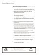
1 11 2 3 4 10 5 9 8 7 6
1 Scope of Delivery What items are supplied depends on your order. Prior to setting up, please check that all the required parts are present. This description refers to a special sewing machine, of which all individual components can completely be delivered by Dürkopp Adler AG.
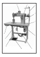
Observe the punch-marks of the table plate! 1 13 15 4,5x15 (x 4) 2 14 12 3 11 4 5 3,5x17 (x 6) 6 10 3,9x15 (x 5) 3,5x17 (x 2) 7 9 B8x35 (x 4) 8 6
3 3.1 3.2 Assembling the stand Assembling the stand components (Standard) – Assemble the individual stand components as shown in the illustration. – Adjust the set screws 8 to insure the stability of the stand. Make sure that the stand is safe by insuring that every single foot of the stand touches the ground.
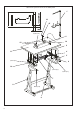
3.3 Setting the working height 1 1 8 – The working height is adjustable between 750 and 900 mm (measured to the upper edge of the table plate). – – Undo screws 1 on the stand braces. Adjust the table plate horizontally to the required working height. To prevent tilting, pull the table plate out or push it in by the same distance on both sides. – Tighten both screws 1.
4 Sewing drives 4. 1 Drive category, type and use The following sewing drives are available: Subclass Clutch motor DC-positioning drive 868-190020 FIR 1147-F.752.3 * Efka DC1550/DA321G 868-290020 FIR 1148-F.752.3 Efka DC1550/DA321G** 868-190322 Efka DC1550/DA321G 868-190341 Efka DC1550/DA321G** 868-290322 868-290341 868-390322 * This clutch motor incorporates an electromagnetic brake that rapidly stops the rotor when it runs on after the motor has been switched off.
4.3 Fitting the sewing drive 8 1 1 2 2 7 6 7 6 5 5 3 4 4.4 4 – Attach the sewing drive 2 with its base 1 on the bottom side of the table plate by screwing the three hexagonal screws (M8 x 15) with washers into the nuts 8 of the table plate bottom. – – Attach the pedal 4 to the stand brace 3. For ergonomic reasons align the pedal 4 as follows: The center of the pedal must be approximately under the needle. There are slots in the stand brace 3 to help align the pedal.
4.5 Fitting the sewing-drive control for machines with Efka DC 1550 / DA 321G 8 7 1 2 – – 4.6 Fix the sewing-drive control 1 with 4 screws underneath the table plate 2. Fix the power supply cable of the sewing-drive control with the traction relief clip 3 underneath the table plate. Fitting the set value initiator – Screw angle 7 under the table plate 8. – Screw the set value initiator 2 onto the angle 7.
5 Assembling the machine head The sewing machine heads of the class 868 can be fitted into the stand horizontally straight as well as inclined. Therefore the positions of the hinges on the machine head and the fastening of the direct drive must be considered. 5.
5.2 Fitting the direct drive 2 1 Position of the motor support for the inclined set-up of the machine Position of the motor support for the straight set-up of the machine 5.3 Tensioning the toothed belt of the direct drive Loosen the screws 1 in order to tighten the toothed belt. The belt tension can be altered by shifting the motor with its support in the oblong hole 2. Afterwards the screws 1 must be tightened again.
5.4 Placing the sewing machine head on the stand 2 1 3 – – – – 14 If the sewing machine is equipped with motor on the table plate bottom, place the machine head 1 vertically into the table plate’s cutout. If the machine is equipped with motor on the machine head, incline the machine head 2 in order to place it into the table plate’s cutout. After placing the machine head immediately fix the retaining plate that prevents the machine head from falling out when being tilted.
5.5 Fitting and tensioning the V-belt Only concerns machines with motor on the table plate bottom. 6 2 9 11 10 4 3 1 5 V-belt 2, V-belt pulley 1 and belt guard are part of the drive set – Fix the V-belt pulley 1 on the shaft of the sewing drive. – Put the V-belt on the belt pulley 6 on the machine head. – – Pass the V-belt 2 down through the cutout of the table plate. Tilt the sewing machine head to the back. – – Place the V-belt 2 on the V-belt pulley 1.
5.6 Fitting the belt cover 1 1 4 2 5 – – – – 16 Remove the handwheel 1. When the machine’s motor is situated underneath the table plate mount the belt cover 2 on the machine head . (The belt cover is part of the drive package) When the machine’s motor is situated on the sewing machine head mount the belt cover 4 and 5 . (The belt guard is part of the drive package) Mount the handwheel 1.
5.7 Fitting the oil suction tube 5 2 1 3 4 – Remove the cap from the end of the suction tube 3. – Put the end of the suction tube 3 into the fitting of the cover 1. – Snap the tube into the tube holder 5 in the oil sump 2. – Screw the cover 4 onto the base plate.
5.8 Attaching the knee lever 3 2 The knee lever 2 mechanically raises the sewing foot. – Attach the knee lever 2. – – Undo the screws on the joint 1. Adjust the knee lever so that it can be conveniently operated with the right knee. – Tighten the screws on joint 1 again. – – Undo screw 3. Align the knee-pad. – Tighten screw 3 again.
5.9 Fitting the operating panel 3 4 1 6 5 – Fix the control panel fixing angle 1 together with the thread guide 2. – Remove the valve cap 4. – Lay the power supply cable 5 of the operating panel as follows: Lay the power supply cable behind valve cap 4 and arm cover 3 in the machine arm and down through the table plate cutout 6. Plug in the plug of the connection cable into the socket B776 of the drive control unit. Replace the arm cover 3 and the valve cap 4.
5.10 Fitting the sewing lamp (optional equipment) Caution ! Turning off the main switch does not turn off the current for the sewing lamp. Remove the mains plug before connecting.
The sewing lamp is mounted on the arm cover. In order to do so lift off the arm cover 3. Drill through the fastening holes with a 4,5 mm drill and fasten the holder. – Stick the safety warning label on the front of the main switch 7. – Fix the sewing light on the holder. – Lift off the arm cover 3 and the valve cap 4. – Lay the power supply cable in the cutout of the machine arm. – Pass the power supply cable down through the hole in the table plate 6.
6 6.1 Electrical connection General Caution ! All work on the electrical equipment of this special sewing machine may only be carried out by qualified electricians or other appropriately trained persons. While working on the electrical equipment the mains plug must be removed! 6.2 Checking the mains voltage Caution ! The mains voltage must coincide with the rated voltage specified on the model-identification plate. 6.3 Connecting the sewing drive 6.3.1 Connecting the clutch motor – – 6.3.
6.4 Earthing 1 2 The earthing cable 1 is in the machine’s accessory pack. The earthing cable 1 takes static charges from the machine head to earth via the motor base. – Connect the earthing cable 1 to the flat plug 2 (already screwed on the machine head) and lay it through the cable duct to the motor base. – Screw the earthing cable 1 onto the motor base at the point provided. – Additionally attach the earthing cable 1 under the table plate with the nail clamps.
6.5 Connecting the sewing drive to the mains Caution: The sewing machine must be connected to the mains with a plug. Clutch motors must be connected to a 3 x 380 - 415V 50/60Hz or 3 x 220 - 240V 50/60Hz three-phase AC. The connection is done according to the connection diagrams 9800 110002 A or 9800 120009 D. The direct-current positioning actuator is operated with a single-phase alternating current of 190 - 240V 50/60 Hz.
6.7 Connecting the sewing light transformer (optional equipment) 2 1 – Remove the machine’s mains plug. – Pass the mains cable 1 of the sewing-lamp transformer through the cable duct 2 to the main switch. It is connected to the mains-connection side of the main switch (or motor-protection switch). See connection diagram 9800 120009 A or 9800 110002 A or 9800 130014 R. Stick the adhesive label with the safety instruction on the front of the main switch .
6.8 6.8.1 Connecting the direct drive Connecting the Hall-effect sensor (Optional Equipment) Only with DC 1550 drive: · · Motor mounted under the table Gear reduction motor - machine 1,55:1 Attention ! Turn off the main switch. Connect the Hall-effect sensor only with the sewing machine switched off. – 2 – – 26 Fit the Hall-effect sensor 1 onto the machine head. 1 4 3 Check whether a magnet is fitted into the belt pulley 2 of the machine.
– – – B 4 1 M Connect the 9-pole SuB-D plug of the Hall-effect sensor to the bushing “B18" (IPG / HSM / LSM) of the Efka control drive DA321G. Set the correct machine class with parameter F-290 according to the corresponding parameter sheet 9800 331104 PBXX. In order to position the machine correctly and to optimize all functions the following parameters must still be set: Parameter F-111: set to 3.000 rpm or less.
6.8.2 Attaching and connecting the sewing light transformer (optional equipment) – – Remove the machine’s mains plug! Connect the mains cable of the sewing light transformer to the mains input side of the control unit. Caution ! The sewing-light transformer is directly connected to the mains. It is therefore live even when the main switch is switched off. The mains plug must be removed before carrying out any work on the sewing-light transformer, e.g. changing the fuse. 6.8.
6.8.4 Connecting the sockets of the DA321G control unit B 4 1 M B 2 B 8 0 M E B ... 2 B 1 8 B 7 7 6 L S M ... V 8 . . 1 A 6.8.5 Connecting the DA321G control unit – – – – – – Plug the cable from the controller (pedal) into socket B80 of the controls. Plug the cable from the motor sensor 1 into socket B2 of the controls. Plug the cable 2 from the motor into socket B41 of the controls. Plug the cable to the sewing machine into socket A of the control unit. Lay all cables through the cable duct.
6.8.6 Checking the direction of rotation of the sewing drive Caution ! Before putting the special sewing machine into operation, the direction of rotation of the sewing drive must imperatively be checked. Operating the special sewing machine in the wrong direction of rotation can lead to damages. The arrow on the belt guard indicates the correct direction of rotation of the machine.
Position 2 – First push the pedal forward and then completely backwards. – The needle positions in position 2 ( about 66° on the handwheel). – Check the needle position. If one or both needle positions are not correct then carry out the correction of the needle position. (see operating instructions) 6.8.8 Machine-specific parameters 6.8.8.1 General The functions of the sewing-drive control are determined by the program and the parameter settings.
1 2 3 6 4 8 2 10 4 5 6 32 7
7 Pneumatic connection Caution: The pneumatic units will only operate properly at a supply pressure of 8 to 10 bar. The special sewing machine’s operating pressure is 6 bar. Pneumatic-connection pack A pneumatic connection pack for stands with compressed-air maintenance unit is available under order no. 0797 003031.
8 Lubrication 1 2 3 Caution: danger of injury ! Oil can cause skin eruptions. Avoid protracted contact with the skin. In the event of contact, thoroughly wash the affected area. CAUTION ! The handling and disposal of mineral oil is subject to legal regulation. Deliver used oil to an authorised collection point. Protect your environment. Take care not to spill oil.
9 Sewing test A sewing test must be carried out when setting-up is complete. – Insert the mains plug. Caution: danger of injury ! Turn off the main switch. The needle and looper threads may only be threaded with the sewing machine switched off. – – – – – – – – – Thread the bobbin-winder thread (see operating instructions). Turn on the main switch. Lock the sewing feet in lifted position (see operating instructions). Fill the bobbin at low speed. Turn off the main switch.
36