DS7000Q GENERATOR User Manual REV: DS7000Q-05252018 This manual provides information regarding the operation and maintenance of these products. We have made every effort to ensure the accuracy of the information in this manual. We reserve the right to change this product at any time without prior notice. 5800 Ontario Mills Pkwy Ontario, CA 91764 USA www.duromaxpowerequipment.
CONTENTS 1. Introduction Introduction ..................................................................................................................... 6 General Safety Procedures ............................................................................................ 7 Quick Start Guide........................................................................................................... 10 Generator Components....................................................................................
CONTENTS 5. Maintenance and Care Maintenance Schedule................................................................................................... 36 Maintenance Log ........................................................................................................... 37 Checking the Oil ............................................................................................................. 38 Changing the Oil..................................................................................
INTRODUCTION DuroStar has cemented its reputation as one of the markets leading power equipment companies who are headquartered in the US. All of our products are manufactured to the strictest guidelines and go through countless testing in all phases of production. Evolving our strong engine line, DuroStar has complemented its offerings to include Pressure Washers, Water Pumps, Engines and now offering V-Twin engines.
GENERAL SAFETY PROCEDURES SAFETY ALERT SYMBOL The safety alert symbol is used with one of the safety words (DANGER, CAUTION, or WARNING) to alert you of hazards. Please pay attention to these hazard notices both in this manual and on the generator. Please familiarize yourself with the following safety symbols and words: ●● DANGER: Indicates a hazard that will result in serious injury or death if instructions are not followed.
GENERAL SAFETY PROCEDURES WARNING: This generator may emit highly flammable and explosive diesel vapors, which can cause severe burns or even death. A nearby open flame can lead to an explosion even if not directly in contact with fuel. ●● Do not operate near an open flame. ●● Do not smoke near generator. ●● Always operate on a firm, level surface. ●● Always turn generator off before refueling. ●● Allow generator to cool for at least 2 minutes before removing fuel cap.
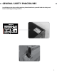
GENERAL SAFETY PROCEDURES In addition to the above safety notices, please familiarize yourself with the safety and hazard markings on the generator.
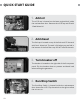
QUICK START GUIDE 1. Add oil The oil fill cap is located on the lower engine block inside the maintenance door. Remove the oil fill cap and fill with 15w40 diesel oil. 2. Add diesel The fuel cap is located on top of the fuel tank. Fill the tank with fresh diesel uel. The tank is full when you see fuel in the bottom of the fuel filter cup. DO NOT overfill the tank. 3. Turn breaker off The breaker is located on the right side of the front power panel.
7. Start generator The key switch is located on the left side of the front power panel. Insert the key and turn to the start position to start the generator. Allow the key to return to the run position once started. 8. Check power indicator The power indicator is located to the right of the keyswitch. Ensure the power indicator is lit before powering appliances. 9. Turn breaker on The breaker is located on the right side of the front power panel.
GENERATOR COMPONENTS 3. Lifting Ring 2. Fuel Cap 4. Air Filter 1. Muffler 8. Battery 7. Stop / Run Switch 5. Oil Fill 6. Oil Drain 1. Muffler - Reduces engine emissions and reduces noise 2. Fuel Cap - Allows access to fill the diesel tank. 3. Lifting Ring - Use to lift the generator with a truck crane or winch. 4. Air Filter - a removable element that cleans the air going into the engine. 5. Oil Fill and Dipstick - Use to add or check the engine oil. 6.
11. Power Indicator 10. Low Oil Alert 12. Voltmeter 13. Power Boost 14. Circuit Breaker 9. Engine Switch 19. 120V 3-Prong Receptacle 18. 120V 3-Prong Twist Lock 17. 120/240 4-Prong Twist Lock 16. Ground Terminal 15. 12V DC Charging Posts 12. Volt Meter - Provides reading of voltage output. 13. Power Boost – DuroStar exclusive Power Boost doubles the amperage available in “120v Only” for heavy loads like RV air conditioners. 14.
PACKAGE CONTENTS Your generator comes with the items listed below. Please check to see that all of the following items are included with your generator. Double Sided Screw Driver Spanner Spark Plug Wrench Phillips and slot blade screwdriver used for generator maintenance. Assorted wrenches used in generator maintenance and assembly. Commonly 8mm, 10mm, 13mm, and 15mm. Used in spark plug maintenance, inspection, and installation.
GENERATOR SETUP Proper setup of your generator will get you going as soon as possible while making sure you and your equipment are safe and cared for.
GENERATOR SETUP Step 1 - Adding Oil The generator requires engine oil to operate properly. The generator, when new from the package contains no oil in the crankcase*. You must add the proper amount of oil before operating the generator for the first time. This amount is equal to the oil capacity of the engine crankcase: Model Number DS7000Q Engine Oil Capacity 54 fl. oz (1.6L) WARNING: Do not apply engine oils with additives or 2-stroke engine oils.
Step 2 - Adding Diesel WARNING: Diesel and fuel fumes are highly flammable. ●● Do not fill tank near an open flame. ●● Do not overfill. Always check for fuel spills. 2. Add Diesel a. Make sure the generator is on a level surface. b. Unscrew fuel cap and set aside (NOTE: the fuel cap may be tight and hard to unscrew). c. Slowly add diesel to the fuel tank. Be careful not to overfill. d. The fuel gauge on the top of the fuel tank indicates how much diesel is in the generator fuel tank. e.
GENERATOR SETUP (CONTINUED) Step 3 - Grounding the Generator 1. Attach grounding wire a. Ground the generator by tightening the grounding nut against a grounding wire. b. Connect the other end to a copper or brass grounding rod that’s driven into the earth. A generally acceptable grounding wire is a No. 12 AWG (American Wire Gauge) stranded copper wire. Grounding codes can vary by location. Please contact a local electrician to check the grounding regulations for your area.
STARTING THE GENERATOR If this is not your first time using the generator there are still steps you should take to prepare it for operation each time you use it. IMPORTANT: At this point you should be familiar with the procedures described in the first portion of this section entitled “GENERATOR SETUP” If you have not yet read this section, go back and read it now.
BEFORE YOU START YOUR GENERATOR Step 1 - Check the oil 1. Check the oil The generator is equipped with an automatic shutoff to protect it from damage due to low oil. Nonetheless, you should check the oil level of the engine before each use to ensure that the engine crankcase has a sufficient amount. To check the oil level: a. Make sure the generator is on a level surface. b. Unscrew the oil filler/dipstick cap. c. With a dry cloth, wipe the oil off of the stick on the inside of the cap. d.
Step 2 - Check the fuel level 1. Check Fuel Level Before starting the generator, check to see that there is sufficient diesel in the fuel tank. The fuel gauge on top of the tank will give a rough estimate of the diesel level. The gauge will appear white then fill red as the tank is filled. Note: Fuel gauge may not register with less than 1/3 fuel tank full. WARNING: Diesel and diesel fumes are highly flammable. ●● Do not fill tank near an open flame.
STARTING THE GENERATOR Starting the Generator 1. Shut breaker off The breaker is located on the right side of the front power panel. Flip the breaker down to prevent accidental load when starting the generator. 2. Run/Stop Switch The Run/Stop Switch is located inside the mainentance door above the oil fill. Flip the switch to the right to allow the unit to run. 3. Turn engine switch to START The key switch is located on the left side of the front power panel.
4. Check power indicator The power indicator is located to the right of the keyswitch. Ensure the power indicator is lit before powering appliances. 6. Return engine switch to RUN The key switch is located on the left side of the front power panel. Insert the key and turn to the start position to start the generator. Allow the key to return to the run position once started.
STARTING THE GENERATOR (CONTINUED) Starting the Generator - Remote Start 1. Turn the breaker ON The breaker is located on the right side of the front power panel. Flip the breaker down to prevent accidental load when starting the generator. 2. Run/Stop Switch The Run/Stop Switch is located inside the mainentance door above the oil fill. Flip the switch to the right to allow the unit to run. 3. Turn engine switch to START The key switch is located on the left side of the front power panel.
4. Open the remote Open the remote by sliding the cover down. Extend the antenna 5. Start the generator Press the start button at the top with the lightening bolt to start the generator. WARNING: Operating the starter motor for more than 5 seconds can damage the motor. If the engine fails to start, press the stop button and wait 10 seconds before operating the starter again.
USING THE GENERATOR If this is not your first time using the generator there are still steps you should take to prepare it for operation each time you use it. IMPORTANT: At this point you should be familiar with the procedures described in the first portion of this section entitled “GENERATOR SETUP” If you have not yet read this section, go back and read it now.
USING THE GENERATOR AC Usage ●● You may connect electrical devices running on AC current according to their wattage requirements. ●● The chart below shows the rated and surge wattage of your generator according to its model number. ●● The rated wattage corresponds to the maximum wattage the generator can output on a continuous basis. ●● The surge wattage corresponds to the maximum amount of power the generator can output for a short period of time.
Tool or Appliance Rated (Running) Watts Additional Surge Watts Electric water heater (40 gal) 4000 0 Hot plate 2500 0 Radial arm saw 2000 2000 Electric Stove 1500 0 Circular Saw 1500 1500 Air compressor (1 HP) 1500 3000 Window air conditioner 1200 1800 Miter saw 1200 1800 Microwave 1000 2000 Well water pump 1000 1500 Reciprocating saw 960 1040 Sump pump 800 1200 Refrigerator freezer 800 1200 Furnace blower 800 1300 Computer 800 0 Electric drill 600 900 Tele
USING THE GENERATOR (CONTINUED) Connecting a load to the generator NOTE: Be sure to attach devices to the correct receptacle (outlet). ●● 120v devices can be directly connected to the 120v ONLY receptacles. ●● 120v devices can be connected to the 120/240v receptacle using an appropriate adapter. ●● 240v devices can ONLY be connected the 240v receptacle. CAUTION: Do not connect 50Hz or 3-phase loads to the generator. 1. Plug in devices Plug in devices to the appropriate receptacle.
Voltage Selector Switch This generator features Power Boost Technology, which gives the user the ability to double the power in the generator for more heavy duty applications. POWER BOOST The voltage selector switches the dual 120v AC windings of the generator TECHNOLOGY to produce “120V ONLY” or “120/240V”. If a 240V appliance is connected to the 4-prong receptacle, the switch must be in the “120/240V” position.
USING THE GENERATOR (CONTINUED) DC Usage CAUTION: The DC receptacle is for recharging 12 Volt automotive-type batteries only. Do not connect any other device to this receptacle. CAUTION: Never try to jump start a car with your generator. 1. Connect the battery Connect one charging wire to the positive terminal on the battery and the other charging wire to the negative terminal on the battery. 2.
4. Connect negative receptacle Carefully connect the free end of the negative wire to the negative receptacle on the generator. 5. Disconnecting When disconnecting, always disconnect the wires from the generator first to avoid a spark. DANGER - Stored batteries emit highly explosive hydrogen gas when charged. Batteries also contain acid, which can cause severe chemical burns. DANGER - Do not allow open flames or cigarettes nearby for several minutes after charging a battery.
MAINTENANCE AND CARE Proper maintenance and storage of your generator is essential to ensure trouble free use of your generator when you need it. By following the maintenance and care requirements, you can keep your generator running smooth and efficient for years to come.
MAINTENANCE AND CARE Proper routine maintenance of your generator is essential for safe, economical, and trouble-free operation. It will also help reduce air pollution. WARNING: Improper maintenance, or failure to correct a problem before operation, can cause a malfunction in which you can be seriously injured or killed. Always follow the inspection and maintenance recommendations and schedules in this instruction manual. ●● Make sure the engine is off before you begin any maintenance or repairs.
MAINTENANCE LOG Date Generator Hours Maintenance Performed 37
MAINTENANCE AND CARE (CONTINUED) Checking the oil 1. Check the oil The generator is equipped with an automatic shutoff to protect it from damage due to low oil. Nonetheless, you should check the oil level of the engine before each use to ensure that the engine crankcase has a sufficient amount. To check the oil level: a. Make sure the generator is on a level surface. b. Unscrew the oil filler/dipstick cap. c. With a dry cloth, wipe the oil off of the stick on the inside of the cap. d.
Changing the oil Worn out or dirty oil does not cool the generator properly and can lead to catastrophic engine damage. In addition to regular oil changes, it is necessary to drain the oil from the crankcase if it has become contaminated with water or dirt. 2. Remove drain plug Using a hex wrench, unscrew the oil drain plug, which is located on the crankcase underneath the oil filler/dipstick cap. Allow all the oil to drain from the generator. 2.
MAINTENANCE AND CARE (CONTINUED) Cleaning the air cleaner Routine maintenance of the air cleaner helps maintain proper airflow to the carburetor. Check that the air cleaner is free of excessive dirt after every use. Note: Improper maintenance may cause less air to enter the engine or dirty air to enter the engine causing overheating and engine wear. 1. Open filter housing Remove the 4 bolts on the right side of generator and remove the cover to expose the air filter. 2.
4. Renstall the element Reinstall the still clean, or new, element in the air cleaner base and secure it with the retaining nut. 5. Reinstall the filter cover Place the air filter cover on the air filter base and tighten the wingnut securely. 6. Reinstall filter housing Reinstall the filter housing on the right side of the generator and secure with the 4 bolts.
SPECIFICATIONS AC Rated Wattage 5500W AC Surge Wattage 7000W AC Rated Voltage 120/240V AC Rated Frequency 60 Hz AC Phase Single DC Voltage 12V DC Amperage 8.3A Dimensions LENGTH 38in. WIDTH 22in. HEIGHT 30in. Engine Type 4-Stroke OHV Forced-Air Ignition System Non-Contact Transistor Displacement 418cc Starting Type Electric Fuel Tank Capacity 3.8 US Gal. (14.5L) Oil Capacity 54 fl. oz. (1.1L) Run Time @ 50% 10 hr.
TROUBLESHOOTING This section of the manual is to help you troubleshoot problems with your generator.
TROUBLESHOOTING Mode Engine will not start Engine runs, but there is no electrical output. Generator runs, but does not support all electrical devices connected.
TROUBLESHOOTING (CONTINUED) Changing / Inspecting the AVR The AVR regulates power from the generator. If the generator is overheated or overloaded, the AVR may be damaged and require replacement. 1. Remove rear cover Remove the 4 bolts of the rear cover then pull the cover off the generator. 2. Remove AVR bolts Remove the 2 bolts holding the AVR. 3. Disconnect AVR wire clip Disconnect the wire clip.
Changing / Inspecting the AVR (Continued) 4. Install new AVR Install the new AVR with the 2 bolts. 5. Reconnect the AVR wire clips Insert and connect the 2 wires clips from the AVR, be sure to connect them securely. 6. Reinstall rear cover Replace the rear cover and tighten the 4 bolts securely.
WIRING DIAGRAM 48
WARRANTY 3-year Warranty All DuroMax/DuroStar Power Equipment warrant the original purchasers to a 3-year Parts Warranty (Residential Use ONLY: Unusually heavy or commercial use is covered for a period of 1-year) in the event of failure due to defects in electrical or mechanical components. Freight on any items submitted for replacement or repair under the Warranty are the responsibility of the equipment owner. This warranty is non-transferable and only valid to the original purchaser.
OWNER’S WARRANTY RESPONSIBILITIES: ●● As the small off-road engine owner, you are responsible for performance of the required maintenance listed in your owner’s manual. DuroMax Power Equipment recommends that you retain all receipts covering maintenance on your small off-road engine, but DuroMax Power Equipment cannot deny warranty solely for the lack of receipts or your failure to ensure the performance of all scheduled maintenance.
WARRANTY (CONTINUED) 2. Any warranted part that is scheduled only for regular inspection in the Owner’s Manual must be warranted for the warranty period stated above. A statement in such written instructions to the effect of “repair or replace as necessary” will not reduce the period of warranty coverage. Any such part repaired or replaced under warranty must be warranted for the remaining warranty period. 3.
Exhaust Emission Warranty Parts List. 1. Fuel Metering System i. Carburetor and internal parts (and/or pressure regulator or fuel injection system). ii. Air/fuel ratio feedback and control system. iii. Cold start enrichment system. 2. Air Induction System i. Controlled hot air intake system. ii. Intake manifold. 3. Ignition System i. Spark Plugs. ii. Magneto or electronic ignition system. iii. Spark advance/retard system. 4. Air Injection System i. Air pump or pulse valve. ii.
CUSTOMER SERVICE DuroStar Power Equipment is comitted to ensuring that our products perform when they need to. Our generators are your lifeline in the event of an emergency. Should you have any problems, please contact our customer service department: DUROSTAR POWER EQUIPMENT 5800 Ontario Mills Parkway Ontario, CA 91764 Customer Service: 844-DUROMAX Customer Service Hours: 8-5pm PST Website: www.duromaxpowerequipment.com Email: customer_service@duromaxpowerequipment.
5800 Ontario Mills Parkway Ontario, CA 91764 United States 844-DUROMAX