
User Manual

12
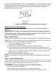
Once you have determined what electrical devices you will be powering with the generator,
connect these devices according to the following procedure:
2. Switch the circuit breaker to the "ON" position.
3. Turn on the connected electrical devices in the order of the amount of power they
require beginning with the device with the highest rated Wattage requirement.
CAUTION: Do not connect 50Hz or 3-phase loads to the generator.
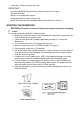
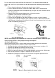
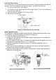
Figure 11- Receptacles available on the generator
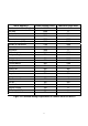
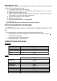
SOME NOTES ABOUT POWER CORDS
Long or thin cords can drain the power provided to an electrical device by the generator.
When using such cords, allow for a slightly higher rated wattage requirement by the electrical
device. See Figure 12 for recommended cords based on the power requirement of the
electrical device.
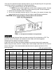
Device Requirements Max. Cord Length (ft) by Wire Gauge
Amps
Watts
(120V)
Watts
(240V)
#8 wire #10 wire #12 wire #14 wire #16 wire
2.5 300 600 NR 1000 600 375 250
5 600 1200 NR 500 300 200 125
7.5 900 1800 NR 350 200 125 100
10 1200 2400 NR 250 150 100 50
15 1800 3600 NR 150 100 65 NR
20 2400 4800 175 125 75 50 NR
Change the Voltage Selector Switch only after turning the AC circuit breaker to OFF. The
generator may be damaged if you attempt to switch modes while drawing power.
*NR= not recommended
40 4800 9600 90 NR NR NR NR
30 3600 7200 125 65 NR NR NR
25 3000 6000 150 100 60 NR NR
Figure 12-Maximum Extension Cord Figure 12-Maximum Extension Cord Lengths byLengths by Pow Poweer Requirement r Requirement
standard 120 Volt, single phase, 60 Hz loads only to the 120 Volt receptacle.
Be sure to attach appliances to the correct receptacle (outlet). Connect
a. NOTE:
1. Plug in each electrical device with the device turned off.