
User Manual


19
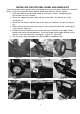
1. Place the bottom of the generator cradle on a flat, even surface. Temporarily place
unit on blocks to ease assembly.
(see figure 22 ).
2. Secure the support leg to the cradle with cap screws (M8 x 16) and lock nuts (M8)
5. Position the lower handle lock on the frame and secure with bolt. Insert upper handle
bracket and secure with provided bolts. Insert the handle into the upper bracket secure
with pin. Insert and secure the retaining pin. ( Figure 26 - Figure 30 ).
23 ).
Figure 22 Figure 23 Figure 248
Figure 25 Figure 26 Fig ur8e 27
Figure 28 Figure 29 Fig ur8e 30
6. The unit comes with solid rubber tires which require no additional care.
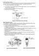
INSTALLING THE OPTIONAL WHEEL AND HANDLE KIT
4. Slide a wheel and a flat washer over the axle, then secure the wheel with a retaining pin
(see Figure 24 , Figure 25 ).
3. Secure the axle to the cradle with cap screws (M8 x 16) and lock nuts (M8) (see fig ure
If you have purchased the optional wheel and handle kit for your unit, please follow the instructions
below. If you have not purchased the optional wheel and handle kit, skip this section.