Model: XP2700PW Gasoline Pressure Washer OPERATOR’S MANUAL Tel:800-629-4329 Email: support@duromaxpowerequipment.
TABLE OF CONTENTS Introduction ..............................................................................................................................................................................3 Safety Rules .............................................................................................................................................................................4 Safety Symbols ......................................................................................................
INTRODUCTION Thank you for purchasing this superior quality pressure washer from DuroMax. When operating and maintaining this product as instructed in this manual, your pressure washer will give you many years of reliable service. Product Specifications: This pressure washer operates at 2700PSI with a flow rate of 2.3 gallons per minute. This high end residential use system features a 180cc Ducar engine, no flat foam filled tires, 25’ high pressure hose, and 4 quick-connect nozzles.
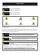
SAFETY RULES Safety Symbols WARNING! Indicates a potentially hazardous situation which could result in serious injury or death if not avoided. CAUTION! Indicates a potentially hazardous situation which could result in damage to equipment or property. Risk of explosion Slippery surface Risk of electric shock Hot surface Eye protection Safety Instructions The manufacturer cannot anticipate every possible hazardous circumstance that the user may encounter.
SAFETY RULES WARNING! To reduce the risk of injection, injury or possible amputation, never direct water pressure • • • • • • • • towards people or pets. The high pressure stream of water produced can cut through skin and underlying tissue. Never squeeze the trigger or point the spray gun at other people, animals, plants, or fragile objects such as glass, even if the engine is stopped. This unit is not a toy. Keep unit away from children and pets. Do not leave spray gun unattended while unit is running.
SAFETY RULES WARNING! Stay alert and use common sense. Do not operate this unit if you are under the influence of alcohol, drugs, medication or you feel tired. Pull cord recoils rapidly and pulls arm towards engine faster than you can let go which could result in injury. Always relieve pressure from spray gun before pulling starter cord, including every failed attempt to start engine. To avoid recoil, pull starter cord slowly until resistance is felt, then pull rapidly.
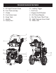
PRESSURE WASHER FEATURES A - 25’ High Pressure Hose B - Fuel Tank and cap C - Choke D - Fuel Valve Lever E - Soap Tank F - Handle G - Spray Gun H - Locking Trigger I - Pull Cord J - Engine On/Off Switch K - Oil Fill and Dipstick L - No Flat Foam Filled Tires M - High Pressure Hose Outlet N - Water Inlet F A G H B C D I J M N K E L 7
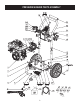
PRESSURE WASHER PARTS ASSEMBLY 8
PRESSURE WASHER PARTS LIST NUMBER ITEM NAME QTY XP2700-P1 180CC Engine 1 XP2700-P2 Bolt M6 x 40mm 1 XP2700-P3 Cap, Soap Tank 1 XP2700-P4 Soap Tank 1 XP2700-P5 Lower "A" Frame assembly 1 XP2700-P6 M8 Self-Lock Nut 1 Rubber Feet 1 XP2700-P7 XP2700-P8 Round Head Bolt M6 x45mm 1 XP2700-P9 Gun Hook 1 XP2700-P10 M6 Self-Lock Nut 1 XP2700-P11 Nut M8 8 XP2700-P12 Engine Mount, Vibration Isolator 4 XP2700-P13 Axle 2 XP2700-P14 Wheels 2 XP2700-P15 Hair Pin 2 XP2700-P16
ASSEMBLY Packing List • • • • • • • • • • • • • Pressure washer Quick start guide Operator’s manual and product registration card Engine manual Spray gun Extension wand with quick-connect fitting High pressure hose Spray nozzles (4) - 0°, 25°, 40° and soap nozzle Spray gun hook (upper) Spray gun hook (lower) Accessory hook Foot (1) Nozzle cleaner WARNING! Do not attempt to assemble or operate this pressure washer until you have read and understood this entire manual.
ASSEMBLY Attaching Foot Assembly (See fig 1) • • • Parts needed - 1 foot, 1 M8 lock nuts. Raise or tilt pressure washer so you can line up foot with the hole located at the centre of the frame. Align the rubber foot with the hole in the frame where the foot is to be located. Attach foot by inserting the bolt from the bottom up and install the acorn nut. Wrench tighten until there is a slight crush on the frame tube.
ASSEMBLY Attaching the Spray Gun (See fig 5 & 6) • • Screw the spray wand and the trigger handle together until they are secure. nut on by turning clockwise until it is hand tight.
ASSEMBLY Adding / Checking Engine Oil (See fig 7) • • • Place pressure washer on a level surface. • • Be sure to replace both dipsticks before attempting to start the engine. To check oil, set pressure washer on a level surface, wipe dipstick clean, then reinsert dipstick without re-threading. Carefully add between 520 ml (17.
ASSEMBLY Connecting Garden Hose to Pressure Washer (See fig 9) • • • • • Inspect inlet screen and remove any debris. Connect hose to water inlet and tighten by hand. There must be a minimum of 10 feet of unrestricted hose between pressure washer and faucet or shut off valve. Turn on water. Purge the system’s pump of air by releasing the safety and squeezing the trigger of the spray gun. CAUTION! Do not run pump without connecting to the water supply and turning water on.
OPERATION Pre-Operation Check List • • • • • • Read and understand this operator manual in its entirety before operating pressure washer. Check oil level and add oil to the proper level if low. Check fuel level and add fuel if needed. Check connections of handle and all hoses to make sure they are secure. Check all hoses for kinks and damage. Check flow of water supply and make sure it is adequate (40 - 80PSI). WARNING! • • • • from dissipating.
OPERATION Pull cord recoils rapidly and pulls arm towards engine faster than you can let go which could result in injury. Always relieve pressure from spray gun before pulling starter cord, including every failed attempt to start engine. To avoid recoil, pull starter cord slowly until resistance is felt, then pull rapidly. WARNING! • • Stopping Pressure Washer (See Fig 13) • • • Turn the on/stop switch to the OFF position. Turn the fuel valve to the OFF position.
OPERATION Using Spray Nozzle (See fig 16) • • • • • To connect or disconnect spray tip, pull back on the quick-connect collar. Insert or remove spray tip then release collar. When spray tip is connected, pull on the spray tip to make sure it is secured. For general cleaning use the 40° spray tip. This option is for cement walkways. For stripping, spot cleaning, blasting, and hard to reach areas use the 25° spray tip.
MAINTENANCE Regular maintenance will extend the life of this pressure washer and improve its performance. The warranty does not cover items that result from operator negligence, misuse, or abuse. To receive full value from the warranty, operator must maintain the pressure washer as instructed in this manual, including proper storage. Before inspecting or servicing this machine, make sure the engine is off and no parts are WARNING! moving. Disconnect the spark plug wire and move it away from the spark plug.
MAINTENANCE Changing Engine Oil Engine oil will drain better if the engine is still warm, but not hot. • Shut off engine. • Clean the area around the oil fill cap/dipstick to keep out debris then remove oil fill cap/dipstick. • Place an oil pan on the ground to catch oil. Remove oil plug then tilt pressure washer back and to the side to empty out the oil from the crankcase. • Once oil is completely drained, return the pressure washer to a level position and install the oil drain plug.
MAINTENANCE Checking Spark Plug • • • • • • • Disconnect the spark plug wire from the spark plug. Before removing the spark plug, clean the area around its base to prevent debris from entering the engine. Clean carbon deposits off the electrode with a wire brush. Check the electrode gap and slowly adjust to 0.80mm (0.031in.) if necessary. Reinstall spark plug and tighten to Torque 22.0 – 26.9 Nm (16-20 ft-lb). Reconnect spark plug wire.
TROUBLESHOOTING PROBLEM CAUSE SOLUTION Engine does not start 1. Out of fuel 2. Engine oil low 3. Spark plug wire disconnected from spark plug 4. Bad spark plug 5. Spark plug wire has shorted 6. Ignition inoperative 1. 2. 3. 4. 5. 6. Engine hard to start 1. Stale fuel or water in fuel 2. Spark plug producing weak spark 3. Excessively rich fuel mixture 1. Engine lacks power and vibrates excessively 1. 1. Engine quits during operation 1. Out of fuel 1.