OWNERS MANUAL Product Support Product Information, Application, Service Info & Warranty Questions Please email us at support@duromaxgenerators.
TABLE OF CONTENTS TABLE OF CONTENTS 2 FEATURES 3 SAFETY INFORMATION 4-6 COMPONENT IDENTIFICATION 7-9 PREPARING THE GENERATOR 9 - 12 STARTING THE GENERATOR GASOLINE 13 STARTING THE GENERATOR PROPANE 14 15 - 18 USING THE GENERATOR 16 WATTAGE REFERENCE CHART MAINTENANCE Service Schedule 19 Checking the Oil 20 Changing the Oil 21 Air Cleaner Maintenance 22 Fuel Filter Cup Cleaning 22 Spark Plug Maintenance 23 Emptying the Gas Tank 23 Storage and Transportation 24 GENERATOR SPECIF
FEATURES Dual Fuel Option, LPG or Gasoline. Durable 7.0 HP, Air Cooled Overhead Valve Engine. Heavy Duty Steel Frame with Four Point Fully Isolated Motor Mounts for Smooth and Quiet Operation. Wheel and Handle Kit for Easy Transporting. Full Power Panel with Engine Shutoff Switch, Volt Meter, Circuit Breaker, and Power Outlets. (2) Fully Protected 120V Outlets & (1) 120V/240V Twist-Lock Outlet. 8 Hour Run Time. All Steel 4.0 Gal. Fuel Tank with EZ-Read Gauge. Low Oil Shut-Off Protects Engine.
GENERAL SAFETY PROCEDURES Please familiarize yourself with the following safety symbols and words: The safety alert symbol is used with one of the safety words (DANGER, CAUTION, or WARNING) to alert you of hazards. Please pay attention to these hazard notices both in this manual and on the generator. DANGER: Indicates a hazard that will result in serious injury or death if instructions are not followed.
GENERAL SAFETY PROCEDURES (Continued) WARNING: This generator produces a powerful voltage, which can result in electrocution. ALWAYS ground the generator before using it (see the "Grounding the Generator” portion of the "PREPARlNG THE GENERATOR FOR USE section). Generator should only be plugged into electrical devices, either directly or with an extension cord. NEVER connect to a building electrical system without a qualified electrician. Such connections must comply with local electrical laws and codes.
GENERAL SAFETY PROCEDURES (Continued) In addition to the above safety notices, please familiarize yourself with the safety and hazard markings on the generator.
PACKAGE CONTENTS Your generator comes with the items listed below. Please check to see that all of the following items are included with your generator.
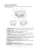
GENERATOR COMPONENTS Please familiarize yourself with the locations and functions of the various components and controls of your generator. . 1. Air Cleaner - a removable, cleanable, oiled, sponge-like element that cleans the air going into the engine. 2. Choke Lever - Allows the airflow into the carburetor to be restricted to assist in starting the engine. 3. Fuel Gauge - Indicates the amount of fuel in the gasoline tank. 4. Fuel Cap - Allows access to fill the gasoline tank. 5.
GENERATOR COMPONENTS (Continued) 16. Fuel Filter Cup - Traps dirt and water in gasoline before it enters the engine. 17. Fuel Valve - On/Off Valve that allows fuel into the engine. 18. Spark plug – Provides ignition to the engine. 19. Muffler – Reduces engine emissions and reduces noise. 20. Propane Tank Connector and Hose – Connects the LPG tank to the LPG Regulator. 21. Propane Regulator and Pressure Release Valve - Provides a regulated LPG Fuel supply to the engine.
PREPARING THE GENERATOR FOR USE (Continued) Figure 2 – Unscrewing the Oil Cap Figure 3 – Adding Oil To add Oil, follow these steps: 1. Make sure the generator is on a level surface. 2. Unscrew the oil filler/dipstick cap from the engine as shown in figure 2. 3. Using a funnel, add the appropriate amount of oil, as found in figure 1, into the crankcase. You will know the crankcase is full when the oil level has reached the lower lip of the opening you have just poured the oil into. (see figure 3.) 4.
PREPARING THE GENERATOR FOR USE (Continued) IMPORTANT: Never use an oil/gasoline mixture. Never use old gas. Avoid getting dirt or water in the fuel tank. Gas can age in the tank and make it hard to start up the generator in the future. Never store generator for extended periods of time with fuel in the tank. Model # Gas Tank Capacity XP4400EH 3.96 US Gallons (15L) Figure 4 - Gas Tank Capacity Step 3 - Ground the Generator WARNING: Failure to properly ground the generator can result in electrocution.
Subsequent Use of the Generator If this is not your first time using the generator there are still steps you should take to prepare it for operation. IMPORTANT: At this point you should be familiar with the procedures described in the first portion of this section entitled "Using the Generator for the First Time." If you have not yet read this section, go back and read it now. Step 1- Check the oil The generator is equipped with an automatic shutoff to protect it from damage due to low oil.
Starting the Generator: Gasoline CAUTION: LPG must be shut off when using gasoline! Gasoline must be shut off when using LPG! Disconnect all electrical loads from the generator before attempting to start! 1. Make sure that the AC circuit breaker is in the OFF position. The generator may be hard to start if a load is connected. 2. Turn the fuel valve lever to the ON position. 3. The choke will need to be closed, slide the choke lever out to the CLOSED position.
Starting the Generator: Propane CAUTION: LPG must be shut off when using gasoline! Gasoline must be shut off when using LPG! Disconnect all electrical loads from the generator before attempting to start! 1. Make sure that the AC circuit breaker is in the OFF position. The generator may be hard to start if a load is connected. 2. Turn the gasoline fuel valve to the "OFF" position. 3. Connect the propane gas hose to the regulator/decompression valve. 4.
Starting the Generator: Propane (Continued) WARNING: WHEN USING THE GENERATOR WITH LPG MAKE SURE THERE IS NO POSSIBLE IGNITION SOURCE CLOSE TO THE GENERATOR. 1. Before using, make sure all of the LPG connectors and hoses are well connected and sealed. 2. Connect electrical devices to generator ONLY after the engine runs smoothly. (There may be remnant gasoline in the carburetor; this can cause unsteady engine performance for several minutes) 3.
Using the Generator (Continued) Once you have found the rated wattage requirement of each electrical device, add these numbers to find the total rated wattage you wish to draw from the generator. If this number exceeds the rated wattage of the generator, DO NOT connect all these devices. Select a combination of electrical devices, which has a total rated wattage lower than or equal to the rated wattage of the generator.
Connecting a Load to the Generator NOTE: Be sure to attach devices to the correct receptacle (outlet). 120v devices can be directly connected to the 120v ONLY receptacles. 120v devices can be connected to the 120/240v receptacle using an appropriate adapter. 240v devices can ONLY be connected the 240v receptacle. 1. Plug in each electrical device with the device turned off. 2. Switch the circuit breaker to the "ON" position. 3.
Choosing the Right Power Cord Long or thin cords can drain the power provided to an electrical device by the generator. When using such cords, allow for a slightly higher rated wattage requirement for the electrical device. See Figure 12 for recommended cords based on the power requirement of the electrical device. DEVICE REQUIREMENTS AMPS WATTS (120V/240V) WIRE GAUGE BY LENGTH (ft.
MAINTENANCE AND CARE The Importance of Maintenance Proper routine maintenance of your generator is essential for safe, economical, and trouble-free operation. It will also help reduce air pollution. Warning Improper maintenance, or failure to correct a problem before operation, can cause a malfunction in which you can be seriously injured or killed. Always follow the inspection and maintenance recommendations and schedules in this instruction manual.
Checking the Oil The generator is equipped with an automatic shutoff to protect it from running on low oil. Nonetheless, you should check the oil level of the generator before each use to ensure that the generator crankcase has a sufficient amount. To check the oil level: 1. Make sure the generator is on a level surface. 2. Unscrew the oil filler/dipstick cap (see figure 14). 3. With a dry cloth, wipe the oil off of the stick on the inside of the cap. 4.
Changing the Oil It is only necessary to drain the oil from the crankcase, other than for regular oil changes, if it has become contaminated with water or dirt. In this case, you can drain the oil from the generator according to the following steps: 1. Place an approved oil disposal container underneath the generator to catch the oil as it drains. 2. Using a 10 mm hex wrench, unscrew the oil drain plug, which is located on the crankcase underneath the oil filler/dipstick cap (see figure 16).
Air Cleaner Maintenance Routine maintenance of the air cleaner helps maintain proper airflow to the carburetor. Occasionally check that the air cleaner is free of excessive dirt. 1. Unhinge the clasps at the top and bottom of the air cleaner cover (see figure 18). 2. Remove the sponge-like elements from the casing. 3. Wipe the dirt from inside the empty air cleaner casing. 4. Wash the sponge-like elements in household dish detergent and warm water. 5. Allow the elements to dry completely. 6.
Spark Plug Maintenance The spark plug is important for proper engine operation. A good spark plug should be intact, free of deposits, and properly gapped. To inspect your spark plug: 1. Pull on the spark plug cap to remove it. 2. Unscrew the spark plug from the generator using the spark plug wrench included with this product (see figure 20). 3. Visually inspect the spark plug. If it is cracked or chipped, discard and replace with a new spark plug. We recommend using a F6RTC spark plug such as NGK BPR5ES. 4.
Storage and Transportation CAUTION: Never place any type of storage cover on the generator while it is still hot. When transporting your generator: Empty the gas tank (see "Emptying the Gas Tank" in the "Maintenance" section). Disconnect the spark plug. Do not obstruct any ventilation openings. Keep the generator in a cool dry area. When storing your generator: If you plan on starting the unit again the same day: 1. 2. 3. 4. Turn off the main breaker. Allow the unit to run 3 - 5 minutes. Turn off the key.
Generator Specifications AC Rated Wattage AC Surge Wattage AC Rated Voltage AC Rated Frequency AC Phase DC Voltage DC Amperage Dimensions (in.) Engine Type Ignition System Displacement Starting Type Fuel Tank Capacity Oil Capacity Run Time @ 50% (Gasoline) Run Time @ 50% (Propane) Noise Level 25 3500W 4400W 120/240V 60 Hz Single 12V 8.3A Length 23.2 Width 17 Height 17 4-Stroke OHV Forced-Air Non-Contact Transistor 210cc Electric 3.96 US Gal. (15L) 20 fl. oz. (0.6L) 12 hr. 16 hr.
Problem Engine will not start Troubleshooting Cause Engine Switch is "Off" Set Engine Switch to "Run" Fuel Valve is "Closed" Turn Fuel Valve to "Open" Choke is open. Engine is out of fuel. Fuel is old or contaminated. Spark Plug is dirty. Spark Plug is broken. Close the Choke Add Fuel Generator runs, but does not support all electrical devices connected. Change Fuel Oil is low.
Wheel Kit Assembly The generator includes a wheel kit for easy transportation. To install the wheel kit: 1. Please the generator on a flat, even surface. Temporarily place blocks under the generator to easy assembly. NOTE: DO NOT flip the generator upside down to install the wheel kit. 2. Secure the support legs to the frame with provided bolts and lock nuts. (See figure 22) 3. Secure the axle bracket welded to axle the frame with the provided bolts and lock nuts. (See figure 23) 4.
Changing/Inspecting the Carbon Brushes Remove the 2 bolts on the generator cover. Remove the bolt holding the carbon brush. Remove the 2 wires from the AVR on the carbon brush. Install a new carbon brush with bolt. Insert and connect the 2 wires from the AVR, be sure to connect + and – correctly. Replace the back cover of the generator and secure with the 2 bolts.
Changing/Inspecting the AVR Remove the 2 bolts on the generator cover. Remove the 2 bolts holding the AVR. Disconnect the wire clip. Remove the 2 wires from the AVR on the carbon brush. Install the new AVR with the 2 bolts. Reconnect the wire clip. Insert and connect the 2 wires from the AVR, be sure to connect + and – correctly Replace the back cover of the generator and secure with the 2 bolts.
Maintenance Log Date MODEL: XP4400EH Generator Hrs.
Wiring Diagram 31
Engine Parts 32
Engine Parts 33
Other Generator Parts 34
Other Generator Parts 35
Product Support Product Information, Application, Service Info & Warranty Questions Please email us at support@duromaxgenerators.