U This manual provides information regarding the operation and maintenance of these products. We have made every effort to ensure the accuracy of the information in this manual. We reserve the right to change this product at any time without prior notice. XP7000IH S E R M A N U A L 5800 Ontario Mills Pkwy Ontario, CA 91764 USA www.duromaxpower.
CONTENTS 1. Introduction Introduction ..................................................................................................................... 6 General Safety Procedures ............................................................................................ 8 Carbon Monoxide Safety.............................................................................................. 12 Unit and Purchase Information ..................................................................................
CONTENTS 6. Stopping the Generator Shutting Down the Generator On Gasoline................................................................. 52 Shutting Down the Generator On Propane................................................................. 53 Shutting Down the Generator With the Remote......................................................... 54 7. Maintenance and Care Maintenance Schedule...................................................................................................
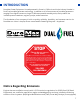
THE DUROMAX WAY The DuroMax Way is more than just a brand, it is our understanding and appreciation of just how important power can be to someone without it… DUROMAX FOR HOME Electricity in our home not only provides comfort but safety as well. From keeping the heat or A/C on to keeping our food cold, power is essential to our daily lives. Inevitability when disaster strikes and we are left without power for a prolonged period of time, our way of life is put at risk.
INTRODUCTION DuroMax Power Equipment is headquartered in Ontario, California and is the industry’s leader in Dual Fuel portable generator technology. In addition to a full assortment of portable generators ranging from digital inverters to large 15,000-watt portable standby units, their product line includes pressure washers, engines, pumps, and accessories. The foundation of our company is built on quality, reliability, durability, and customer service.
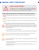
GENERAL SAFETY PROCEDURES SAFETY ALERT SYMBOL The safety alert symbol is used with one of the safety words (DANGER, WARNING, or CAUTION) to alert you of hazards. Please pay attention to these hazard notices both in this manual and on the engine. Please familiarize yourself with the following safety symbols and words: ● DANGER: Indicates a hazard that will result in serious injury or death if instructions are not followed.
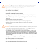
WARNING: This generator may emit highly flammable and explosive gasoline vapors, which can cause severe burns or even death. A nearby open flame can lead to an explosion even if not directly in contact with gasoline. ● Do not operate near an open flame. ● Do not smoke near the generator. ● Always operate on a firm, level surface. ● Always turn the generator off before refueling. ● Allow generator to cool for at least 2 minutes before removing the fuel cap. Loosen cap slowly to relieve pressure in the tank.
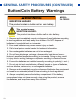
GENERAL SAFETY PROCEDURES (CONTINUED) Button/Coin Battery Warnings AWARNING INGESTION HAZARD MODEL: 3V CR2032 This product contain a button cell or coin battery E;; This symbol means: INGESTION HAZARD: ;3 This product contains a button cell or coin battery. 1. Remove and immediately recycle or dispose of used batteries according to local regulations and keep away from children. Do NOT dispose of batteries in household trash or incinerate. 2. Even used batteries may cause severe injury or death. 3.
In addition to the above safety notices, please familiarize yourself with the safety and hazard markings on the generator.
CARBON MONOXIDE SAFETY Carbon Monoxide Generators are convenient, but they can also be dangerous. All fuelburning appliances and equipment release a poisonous gas called carbon monoxide. Carbon monoxide (also known as CO) can be dangerous for humans and pets, even in small amounts, because it blocks oxygen from getting into your body. Carbon monoxide poisoning can lead to death in a very short time. It is odorless, tasteless and invisible, so you may be exposed without knowing it.
As the only safe way to use a portable generator, taking your generator outside is absolutely mandatory to keep your family safe from carbon monoxide. But there’s even more you can do. By educating yourself about all carbon monoxide risks, you’ll be better prepared to protect your family from this colorless, odorless threat. Visit takeyourgeneratoroutside.com for more information.
UNIT AND PURCHASE INFORMATION Serial Number Serial number The serial number is located on the back of the generator and next to the wheel. Serial number format The serial number will be shown in two parts. The engine model, followed by the serial number. Engine Model: _____________________________________________ Serial Number: _____________________________________________ STAPLE RECEIPT HERE A purchase receipt may be necessary for warranty parts or service in the future.
GENERATOR COMPONENTS To help you get familiar with your new DuroMax generator, please see this component section for easy reference on all the generator’s individual features.
GENERATOR COMPONENTS 3. Fuel Tank 2. Handles 1. Power Panel 4. Right Service Panel 5. Wheels 1. Power Panel - Contains the start switch, plugs, meters, and circuit breakers. 2. Handles - Allow for easy steering during transportation. 3. Fuel Tank - A 3 gallon gasoline fuel tank. 4. Right Service Panel- Allows easy access for changing your generator’s oil. 5. Wheels - Solid wheels allow for easy transportation over any terrain. 6. Fuel Valve - ON/OFF valve that allows gasoline into the engine.
10. Battery Tender 11. CO Alert 9. Start Up Switch 8. Start Button 12. Parallel Ports 7. Multimeter 13. Main Circuit Breaker 6. Fuel Valve 17. 240V 30A Receptacle 14. LPG Inlet 15. Low Idle 16.120V GFCI Receptacles 10. Battery Tender - Easily keep your battery charge when the generator is in storage by using the included battery tender. 11. CO Alert - Shuts down the engine in the event of CO buildup. 12. Parallel Ports - Allow you to combine the output of two generators for maximum power. 13.
PACKAGE CONTENTS Your generator comes with the items listed below. Please check to see that all of the following items are included with your generator. Oil Funnel w/ Hose Battery Tender Used to add oil to the generator without messy spills. Used to charge the battery when in storage Double-Sided Screw Driver Propane Regulator w/ Hose Phillips and slot blade screwdriver used for generator maintenance. Used to provide a regulated propane supply to the propane inlet.
GENERATOR SETUP Proper setup of your generator will get you going as soon as possible while making sure you and your equipment are safe and cared for.
GENERATOR SETUP (CONTINUED) Step 1 - Connect the Battery 1. Remove maintenance cover a. Remove the left maintenance cover by removing both thumbscrews and removing the cover. 2. Locate the battery cables a. Locate the battery cables above and behind the battery. One side is connected to the housing and the other end is attached to the battery terminals. b. Route both battery ends forward to clip together. 3. Connect battery cables a.
Step 2 - Adding Oil The generator requires engine oil to operate properly. The generator, when new from the package, contains no oil in the crankcase*. You must add the proper amount of oil before operating the generator for the first time. This amount is equal to the oil capacity of the engine crankcase: Model Number XP7000iH Engine Oil Capacity 23.7 fl. oz. (0.
GENERATOR SETUP (CONTINUED) Step 3 - Adding Gasoline (Optional) Add gasoline a. Make sure the generator is on a level surface. b. Unscrew gas cap and set aside (NOTE: the gas cap may be tight and hard to unscrew). c. Slowly add unleaded gasoline to the fuel tank. Be careful not to overfill. The fuel gauge on the control center display indicates how much gasoline is in the generator gas tank. d. Replace fuel cap and wipe up any spilled gasoline with a dry cloth.
Step 4 - Grounding the Generator Attach grounding wire a. Ground the generator by tightening the grounding nut against a grounding wire. b. Connect the other end to a copper or brass grounding rod that’s driven into the earth. A generally acceptable grounding wire is a No. 12 AWG (American Wire Gauge) stranded copper wire. Grounding codes can vary by location. Please contact a local electrician to check the grounding regulations for your area.
STARTING THE GENERATOR If this is not your first time using the generator there are still steps you should take to prepare it for operation each time you use it. IMPORTANT: At this point, you should be familiar with the procedures described in the first portion of this section entitled “GENERATOR SETUP” If you have not yet read this section, go back and read it now.
BEFORE YOU START YOUR GENERATOR Step 1 - Check the Oil Check the oil The generator is equipped with an automatic shutoff to protect it from damage due to low oil. Nonetheless, you should check the oil level of the engine before each use to ensure that the engine crankcase has a sufficient amount. To check the oil level: 26 a. Make sure the generator is on a level surface. b. Remove the right hand maintenance cover. c. Unscrew the oil filler/dipstick cap. d.
Step 2 - Check the Gas Level (Optional) Check fuel level If running the engine on gasoline, check to see that there is sufficient gasoline in the fuel tank. The fuel gauge on the control center display will give a rough estimate of the gasoline level. Note: Fuel gauge may not register with less than 1/3 fuel tank full. DANGER 1.5” DO NOT OVERFILL THE GAS TANK OVERFILLING CAN RESULT IN A FIRE, EXPLOSION, OR DEATH. WARNING: Gasoline and gasoline fumes are highly flammable.
STARTING THE GENERATOR Starting the Generator Using Gasoline 1. Turn start switch ON The start switch is located on the top center of the front power panel next to the START button. Press the switch up to the ON position to allow the generator to start. 2. Turn gas valve ON The gas valve is located the left hand side of the panel. Rotate the valve clockwise to the FUEL ON (RUN) position to turn on the gasoline supply. 3.
5. Press the START button The START button is located on the top center of the power panel. Press the button down for 1-3 seconds to start the generator. 6. Turn main breaker ON/Connect The breaker is located in the top right of the front power panel. Flip the breaker up to allow the power to flow to the receptacles. Connect your devices to the receptacles on the front panel. Start with the largest loads first.
STARTING THE GENERATOR (CONTINUED) Starting the Generator Using Propane 1. Connect propane hose The LPG inlet is located on the bottom left of the front panel. Connect the propane hose to both the inlet and the propane tank. Open the propane tank. 2. Turn gas valve ON The gas valve is located the left hand side of the panel. Rotate the valve clockwise to the FUEL ON (RUN) position. 3. Turn main breaker OFF The breaker is located in the top right of the front power panel.
5. Turn start switch ON The start switch is located on the top center of the front power panel next to the START button. Press the switch up to the ON position to allow the generator to start. 6. Press the START button The START button is located on the top center of the power panel. Press the button down for 1-3 seconds to start the generator. 7. Turn main breaker ON/Connect The breaker is located in the top right of the front power panel.
STARTING THE GENERATOR (CONTINUED) Starting the Generator Using Propane WARNING: WHEN USING THE GENERATOR WITH LPG, MAKE SURE THERE IS NO POSSIBLE IGNITION SOURCE CLOSE TO THE GENERATOR. 1. Before using, make sure all of the LPG connectors and hoses are well connected and sealed. 2. Connect electrical devices to the generator ONLY after the engine runs smoothly. (There may be remnant gasoline in the carburetor; this can cause unsteady engine performance for several minutes) 3.
STARTING THE GENERATOR (CONTINUED) Starting the Generator Using Recoil Start 1. Select fuel Follow step 2 on “Starting the Generator Using Gasoline” section if your using gasoline, or steps 1 and 2 on “Starting the Generator Using Propane” section if your using propane. 2. Shut main breaker OFF The breaker is located on the top right of the front power panel. Flip the breaker down to prevent accidental load when starting the generator. 3.
5. Pull the recoil start The recoil start is located on the right side of the generator. Pull the recoil handle slowly until resistance is felt, then quickly pull the recoil handle until fully extended. CAUTION: Release the recoil handle only after the cord has retracted. Releasing the recoil handle while extended may cause harm to yourself or your equipment. 6. Turn main breaker ON/Connect The breaker is located in the top right of the front power panel.
STARTING THE GENERATOR (CONTINUED) Starting the Generator Using Remote Start 1. Select fuel Follow step 2 on “Starting the Generator Using Gasoline” section if your using gasoline, or steps 1 and 2 on “Starting the Generator Using Propane” section if your using propane. 2. Turn main breaker ON The breaker is located in the top right of the front power panel. Flip the breaker up to allow the power to flow to the receptacles. 3.
5. Push the START button The remote start has two buttons, START and STOP. Press the START button two times in succession to start the generator.
USING THE GENERATOR If this is not your first time using the generator, there are still steps you should take to prepare it for operation each time you use it. IMPORTANT: At this point, you should be familiar with the procedures described in the first portion of this section entitled “GENERATOR SETUP”; if you have not yet read this section, go back and read it now.
USING THE GENERATOR AC Usage ● You may connect electrical devices running on AC current according to their wattage requirements. ● The chart below shows the rated and surge wattage of your generator according to its model number. ● The rated wattage corresponds to the maximum wattage the generator can output on a continuous basis. ● The surge wattage corresponds to the maximum amount of power the generator can output for a short period of time.
Tool or Appliance Rated (Running) Watts Additional Surge Watts Electric water heater (40 gal) 4000 0 Hot plate 2500 0 Radial arm saw 2000 2000 Electric stove 1500 0 Circular saw 1500 1500 Air compressor (1 HP) 1500 3000 Window air conditioner 1200 1800 Miter saw 1200 1800 Microwave 1000 2000 Well water pump 1000 1500 Reciprocating saw 960 1040 Sump pump 800 1200 Refrigerator freezer 800 1200 Furnace blower 800 1300 Computer 800 0 Electric drill 600 900 Tele
USING THE GENERATOR (CONTINUED) Connecting the Generator to a Home Interlock kit ● Choose what circuits you want to run. ● Requires an electrician to install, but you have the flexibility of switching up your circuits depending on your power needs. ● More hands-on, and some electrical knowledge is needed so you don’t overload the generator. Transfer switch ● Automatically switches power over to your generator during an outage. Requires an electrician to install.
USING THE GENERATOR (CONTINUED) Connecting a Load to the Generator NOTE: Be sure to attach devices to the correct receptacle (outlet). ● 120V devices can be directly connected to the 120V ONLY receptacles. ● 120V devices can be connected to the 120/240V receptacle using an appropriate adapter. ● 240V devices can ONLY be connected to the 240V receptacle. CAUTION: Do not connect 50 Hz or 3-phase loads to the generator. 1. Plug in devices Plug in devices to the appropriate receptacle.
Choosing the Right Power Cord Long or thin cords can drain the power provided to an electrical device by the generator. When using such cords, allow for a slightly higher rated wattage requirement for the electrical device. See the table below for recommended cords based on the power requirement of the electrical device. DEVICE REQUIREMENTS WIRE GAUGE BY LENGTH (ft.
USING THE GENERATOR (CONTINUED) Using the Digital Multimeter 1. Runtime/Total Hours 2. Voltage 3. Load 4. Gasoline Fuel Meter 5. Frequency 1. Runtime/Total Hours – This portion of the display will automatically switch between the current runtime and total runtime hours of the unit. 2. Voltage – This portion of the display will show the voltage output of the generator. 3. Load - This portion of the display shows the current load output in kW. 4.
Low Idle Usage Low Idle The low idle feature automatically lowers the RPM of the generator based on the current load to help conserve fuel and lower the noise of the generator. Turn on the low idle for better fuel efficiency and to make the generator quieter. CAUTION: Some high surge items may not work correctly with low idle.
USING THE GENERATOR (CONTINUED) Using the Battery Tender The generator battery can steadily lose charge during longer periods of storage. Plug the provided trickle charger in to ensure your battery is maintained and ready for use if needed. CAUTION: Avoid allowing the 12V battery to drop below 11.6V of charge, this can cause permanent damage to the battery cells. Connect the battery tender a. The battery tender outlet is located to the right of the control center display.
STOPPING THE GENERATOR This section will cover the recommended shut off procedure for stopping the generator on various fuels.
STOPPING THE GENERATOR Shutting Down the Generator On Gasoline 1. Flip the main breaker OFF The breaker is located on the top right of the front power panel. Flip the breaker down to the OFF position. 2. Run the generator Allow the generator to run for 3-5 minutes. 3. Turn the generator OFF Hold the start button for 3 seconds to shut off the generator. 4. Turn start switch OFF Turn the start switch to the OFF position.
Shutting Down the Generator On Propane 1. Turn OFF the main breaker Move the main breaker to the OFF position. 2. Run the generator Allow the generator to run for 3-5 minutes. 3. Turn start switch OFF Turn the start switch to the OFF position. 4. Close the propane tank valve Turn your propane tank valve to the CLOSE position.
STOPPING THE GENERATOR (CONTINUED) Shutting Down the Generator With the Remote 1. Flip the main breaker OFF The breaker is located on the top right of the front power panel. Flip the breaker down to the OFF position. 2. Run the generator Allow the generator to run for 3-5 minutes. 3. Hold the stop button Hold the STOP button to shut off the generator. 4. Turn start switch OFF Turn the start switch to the OFF position.
MAINTENANCE AND CARE Proper maintenance and storage of your generator are essential to ensure trouble-free use of your generator when you need it. By following the maintenance and care requirements, you can keep your generator running smoothly and efficiently for years to come.
MAINTENANCE AND CARE Proper routine maintenance of your generator is essential for safe, economical, and trouble-free operation. It will also help reduce air pollution. WARNING: Improper maintenance, or failure to correct a problem before operation, can cause a malfunction in which you can be seriously injured or killed. Always follow the inspection, maintenance recommendations, and schedules in this instruction manual. ● Make sure the engine is off before you begin any maintenance or repairs.
Break-In Period As the best practice for any new combustion motor it’s recommended to perform the break in procedure as follows: ● Run the generator for the first 6-8 hours on conventional oil, then change the oil. After the break-in period synthetic oil may be used. ● During the break in period of the first 6-8 hours keep the generator load under 50% for optimal results. ● Check and clean the air filter if necessary after the break-in period.
MAINTENANCE AND CARE (CONTINUED) Checking the Oil Check the oil The generator is equipped with an automatic shutoff to protect it from damage due to low oil. Nonetheless, you should check the oil level of the engine before each use to ensure that the engine crankcase has a sufficient amount. To check the oil level: a. Make sure the generator is on a level surface. b. Unscrew the oil filler/dipstick cap. c. With a dry cloth, wipe the oil off of the stick on the inside of the cap. d.
MAINTENANCE AND CARE (CONTINUED) Changing the Oil CAUTION: Worn out or dirty oil does not cool the generator properly and can lead to catastrophic engine damage. In addition to regular oil changes, it is necessary to drain the oil from the crankcase if it has become contaminated with water or dirt. 1. Remove maintenance cover Unscrew both plastic thumbscrews on the right hand side maintenance cover; then remove the maintenance cover from the generator. 2.
4. Replace cap Replace the oil drain cap. 5. Add new oil Remove oil fill cap and add new oil to engine. 6. Replace maintenance cover Replace maintenance cover and tighten both thumbscrews to secure the cover.
MAINTENANCE AND CARE (CONTINUED) Cleaning the Air Filter Routine maintenance of the air cleaner helps maintain proper airflow to the carburetor. Check that the air cleaner is free of excessive dirt after every use. CAUTION: Improper maintenance may cause less air to enter the engine or dirty air to enter the engine causing overheating and engine wear. 1. Remove maintenance cover Remove the left maintenance cover by removing both thumbscrews and removing the cover. 2.
4. Wash cleaner element Wash the sponge-like elements in household dish detergent and warm water. 5. Dry cleaner element Pat dry on a dry cloth and allow the elements to dry completely. 6. Add engine oil to elements Soak the dry elements in a small amount of engine oil. Ring out any excess oil. 7. Replace elements in casing Replace the sponge-like elements in the air filter casing and replace the cover; then secure the air filter cover with the thumbscrew.
MAINTENANCE AND CARE (CONTINUED) Spark Plug Maintenance SPARK PLUG CONSULT MANUAL BEFORE REMOVING The spark plug is important for proper engine operation. A good spark plug should be intact, free of deposits, and properly gapped. CAUTION: Improper maintenance may cause reduced fuel economy, misfires, trouble starting, or damage to the spark plug threads. 1. Remove maintenance cover Remove the left maintenance cover by removing both thumbscrews and removing the cover. 2.
4. Remove spark plug Unscrew the spark plug from the generator using the spark plug wrench included with this product. 5. Inspect spark plug and gap Visually inspect the spark plug. If it is cracked or chipped, discard and replace it with a new spark plug. We recommend using an NGK BPR6ES spark plug. Measure the plug gap with a gauge. The gap should be 0.7-0.8 mm (0.028-0.031 in). 6.
MAINTENANCE AND CARE (CONTINUED) Emptying the Gas Tank If you have been using gasoline in your generator, before storing your generator for extended periods of time you should drain your generator fuel tank of gasoline. CAUTION: Do not store fuel from one season to another. Gasoline sold at the pump today contains additives such as ethanol that even when stored properly may damage the fuel system components. 1.
4. Turn fuel valve ON Turn the fuel valve clockwise to the FUEL ON position and allow the gas to fully drain from the gas tank. Once the fuel is fully drained turn the fuel valve counter-clockwise to the FUEL OFF position. 5. Tighten carburetor drain screw Tighten the drain screw with the provided screwdriver to stop the flow of fuel from the carburetor bowl. 6. Replace maintenance cover Reinstall the maintenance cover and install the thumbscrews to secure.
MAINTENANCE AND CARE (CONTINUED) Transporting the Generator 1. Empty the gas tank Fully drain your gas tank as shown in “Emptying the Gas Tank” on page 66-67. 2. Disconnect the spark plug Pull on spark plug cap to disconnect spark plug from ignition wire as shown in “Spark Plug Maintenance” steps 1-3 on page 64. CAUTION: Do not obstruct any ventilation openings and keep the generator in a cool dry area. CAUTION: Never place any type of storage cover on the generator while it is still hot.
Storing the Generator for Use Within 30 Days 1. Add fuel stabilizer to gas tank Add fuel stabilizer to gas tank to help preserve gasoline for longer storage period. 2. Flip main breaker OFF and run Turn OFF the main breaker and allow the generator to run for 3-5 minutes. 3. Turn fuel valve OFF and run dry Turn fuel valve counter-clockwise to the OFF position and allow unit to run until it stalls out. 4. Flip start switch OFF/Store Turn the start switch to the OFF position and store the generator.
MAINTENANCE AND CARE (CONTINUED) Storing the Generator for Longer Than 30 Days 1. Add fuel stabilizer to gas tank Add fuel stabilizer to gas tank to help preserve gasoline for longer storage period. 2. Flip main breaker OFF and run Turn OFF the main breaker and allow the generator to run for 3-5 minutes. 3. Turn fuel valve OFF and run dry Turn fuel valve to OFF position and allow unit to run until it stalls out. 4.
5. Remove spark plug Remove spark plug as shown in “Spark Plug Maintenance” on page 64. 6. Add oil to cylinder Add 2 tablespoons of 10W-30 motor oil directly into the spark plug hole on each side, and pull the recoil to lubricate cylinder. After lubricating cylinder reinstall the spark plug. 7. Connect the battery tender Connect battery tender and leave plugged in to maintain the battery while in storage, as shown on “Using the Battery Tender” on page 49.
SPECIFICATIONS 72 Model Number XP7000iH AC Rated Wattage (Gasoline) 5,500 W AC Rated Wattage (Propane) 5,225 W AC Surge Wattage (Gasoline) 7,000 W AC Surge Wattage (Propane) 6,650 W AC Rated Voltage 120/240V Dimensions 25.1” L x 19.4” W x 21.38” H Weight 128 lbs Recommended Oil 10W-30 Engine Displacement 320 cc Gasoline Capacity 3 gal. (11.4 L) Oil Capacity 23.7 fl. oz. (0.
TROUBLESHOOTING This section of the manual is to help you troubleshoot problems with your generator.
TROUBLESHOOTING Mode Engine will not start Engine runs, but there is no electrical output Generator runs, but does not support all electrical devices connected 74 Description Solution Battery not charged Charge battery Engine switch is in the “OFF” position Turn engine switch to the “ON” position Stale gasoline or water in gasoline Drain entire system and refill with fresh fuel Engine is out of fuel Add fuel Fuel is old or contaminated Change fuel Spark plug is dirty Clean spark plug Spar
WARRANTY 5-Year Warranty All DuroMax Power Equipment warrant the original purchasers to a 5-year Parts Warranty (Residential Use ONLY: Unusually heavy or commercial use is covered for a period of 1-year) in the event of failure due to defects in electrical or mechanical components. Freight on any items submitted for replacement or repair under the Warranty is the responsibility of the equipment owner. This warranty is non-transferable and only valid to the original purchaser.
U.S EPA AND CALIFORNIA EMISSION CONTROL WARRANTY STATEMENT YOUR WARRANTY RIGHTS AND OBLIGATIONS The California Air Resources Board, The United States Environmental Protection Agency (US EPA) and DuroMax Power Equipment, are pleased to explain the emission control system warranty on your 2023-2024 year small off-road engine. In the United States and California, new small off-road engines must be designed built and equipped to meet the State’s stringent anti-smog standards.
WARRANTY (CONTINUED) DEFECTS WARRANTY REQUIREMENTS: (a) The warranty period begins on the date the engine or equipment is delivered to an ultimate purchaser. (b) General Emissions Warranty Coverage.
(6) The owner must not be charged for diagnostic labor that leads to the determination that a warranted part is, in fact, defective provided that such diagnostic work is performed at a warranty station. (7) DuroMax Power Equipment is liable for damages to other engine components proximately caused by a failure under warranty of any warranted part.
WARRANTY (CONTINUED) (i) An air pump or pulse valve. (ii) Valves affecting the distribution of flow. (iii) Distribution manifold. (6) Catalyst or Thermal Reactor System (i) Catalytic converter. (ii) Thermal reactor. (iii) Exhaust manifold. (7) Particulate Controls (i) Traps, filters, precipitators, and any other device used to capture particulate emissions. (8) Miscellaneous Items Used in Above Systems (i) Electronic controls (ii) Vacuum, temperature, and time- sensitive valves and switches.
CUSTOMER SERVICE DEPARTMENT DuroMax Power Equipment is committed to ensuring that our products perform when they need to. Our generators are your lifeline in the event of an emergency. Should you have any problems, please contact our customer service department: DUROMAX POWER EQUIPMENT 5800 Ontario Mills Parkway Ontario, CA 91764 Customer Service: 844-DUROMAX Customer Service Hours: 8-5 pm PST Mon-Fri Website: www.duromaxpower.com Email: customerservice@duromaxpower.
5800 Ontario Mills Parkway Ontario, CA 91764 United States 844-DuroMax REV: XP7000iH-02162024