Gasoline Water Pump Owner’s Manual Max Tool Customer Service customer_service@maxtool.com or call 1-800-629-3325 (option 3) Monday -Thursday 6am to 7pm, Friday - Saturday 6am to 3pm. PST Product Support (Product: information, application & warranty questions) support@maxtool.com or call 1-800-629-3325 (option 3) Monday -Thursday 6am to 7pm, Friday - Saturday 6am to 3pm. PST This manual provides information regarding the operation and maintenance of these products.
CONTENTS ĉ. General Safeguards ĂĂĂĂĂĂĂĂĂĂĂĂĂĂĂĂĂ 1 Ċ. Location of Component Parts ĂĂĂĂĂĂĂĂĂĂĂĂĂ 3 ċ. Operation before Starting Up ĂĂĂĂĂĂĂĂĂĂĂĂĂ 4 Č. Starting of Engine ĂĂĂĂĂĂĂĂĂĂĂĂĂĂĂĂĂĂ 9 č. Use in Highland Areas ĂĂĂĂĂĂĂĂĂĂĂĂĂĂĂĂ 11 Ď. Operation of Water Pump ĂĂĂĂĂĂĂĂĂĂĂĂĂĂ 12 ď. Shutting Down the Engine ĂĂĂĂĂĂĂĂĂĂĂĂĂĂ 13 Đ. Maintenance ĂĂĂĂĂĂĂĂĂĂĂĂĂĂĂĂĂĂĂĂ 14 đ. Transportation and Storage ĂĂĂĂĂĂĂĂĂĂĂĂĂĂ 19 Ē. Troubleshooting ĂĂĂĂĂĂĂĂĂĂĂĂĂĂĂĂĂĂĂ 21 ē.
ĉ. General Safeguards Safety Precautions Please read this operation manual to have a thorough understanding of the content there before use the product. Failure to do so may lead to personal injury or mechanical damage. Before starting the engine, perform inspections according to the procedures described on pre-operation inspections to avoid accidents and damage to your machine.
stored. Do not allow the fuel to overflow the fuel tank. Be sure to recap the tank and tighten it after refueling. When fueling, take care not to spill the gasoline about as the gasoline vapor may easily get ignited to cause a fire hazard. Be sure to remove the spilled gasoline as by wiping before starting the engine.
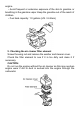
ċ. Operation before Starting Up 1. Connecting the water inlet Connect the water inlet with a commercially available hose, connector and fastener clip. The inlet hose must be a continuous non-foldable structure with a length not more than required and should be placed near to the source of water so as to achieve the pump should be fitted to the end of the hose with the hose connector as shown in the figure below.
2. Connecting the water outlet Connect the water outlet with a commercially available hose, hose connector and fastener clip. Large diameter hoses are the most effective while small ones will increase the flow resistance and reduce the output power of the pump. NOTE: Be sure to the fastener clip is securely fastened to prevent the outlet hose from coming off under high water pressure. 3.Checking the oil level CAUTION: gThe oil is one of the major factors affecting engine performance and life.
Insert the dipstick into the oil filler but not screw it in. Replenish the crankcase with the recommended type of oil until the oil level comes up to the upper most position of the refilled if the existing oil level is found too low. CAUTON: gRunning the engine at a low oil level will cause damage to it. 4. Checking the fuel level Uncap the fuel tank and check the fuel level. Pouring gasoline if the fuel level is found too low.
engine. gAvoid frequent or extensive exposure of the skin to gasoline or breathing in the gasoline vapor. Keep the gasoline out of the reach of children. gFuel tank capacity: 1.0 gallons (US. 3.6 liters) 5. Checking the air cleaner filter element Screw the wing nut and remove the washer and cleaner cover. Check the filter element to see if it is too dirty and clean it if necessary.
6. Checking and filling the pump with cooling water The pump must be filled with water before it is put to operation. CAUTION: gDo not attempt running the pump without cooling water or the pump will get overheated. Extensive running without cooling water may also damage the air tightness of the pump. If the pump is found running dry, stop the engine and pouring in water when it cools down. Č. Starting engine 1. Turn on the fuel tap (by setting it to the ON position). 2. Close the choke.
3. Set the engine switch to the ON position. 4. Turn the throttle control lever slowly to the left. 5. Gently pull up the starter lever until a resistance is felt and then quickly pull it up. CAUTION: gDo not allow the starter lever to retract quickly into the engine. Let it go back gently to avoid damaging the starter.
č.Use in Highland Areas Operation in Highland Conditions In highland areas (with a high ASL elevation), the air-fuel mixture produced by a standard carburetor will be too thick and result in a reduced engine performance and soared fuel consumption. For operation in highland areas, the engine performance may be increased by using a smaller diameter carburetor nozzle and readjusting the carburetor idle speed.
2. Set the throttle to the predetermined RPM. ď. Shutting Down the Engine 1. Set the throttle control lever to the right end. 2. Set the engine switch to the OFF position. 3. Turn off the fuel tap (by setting to the OFF position). NOTE: gTo shut down the engine in an emergency, simply set the engine switch to the OFF position.
Đ. Maintenance Periodic inspections and fine-tuning are simply indispensable to keep the water pump working with high performance and regular maintenance may also lengthen the pump life. Supplied in the table on the next page are intervals at which the schedules maintenance jobs are to be done. WARNING: gBefore any maintenance attempt, be sure to shut down the engine.
Table of Maintenance Schedules Normal Each Per Per Per maintenance time month month month Item perio or 20 or 50 or 100 d hours hours hours Per month or 300 hours ƻ Check engine oil lever ƻ ƻ Replace engine oil lever ƻ Air cleaner check Air cleaner for clean ƻ Spark plug Fuel supply Replace per every two years Wane wheel Pump case cover Water inlet Note: “*” items will be maintained with the help of dealers general power machinery Co., Ltd. 1.
NOTE: Be sure to keep the environment clean when disposing used engine oil. We suggest you collect the waste oil in a container to be sent to a waste disposal site or a recycling service center of spill it in the garbage or on the ground. 2. Maintaining the air cleaner A dirty air cleaner will let less air into the carburetor. To prevent carburetor malfunctions, be sure to maintain the air cleaner periodically.
3. Maintaining the spark plug The recommended type of spark plug is NHSP LD P6RTCU. To ensure normal operation of the engine, the spark plug should have a correct gap and should remain free of carbon deposits. 1) Remove the plug cap. The muffler may be very hot if the engine is still running. Take care not to touch the muffler. 2) Check the spark plug visually. Discard the spark plug if it is obviously worn out or the insulation ring on it is broken or cracked.
screw turn is necessary. CAUTION: g Make sure the spark plug is properly tightened. Improper tightening may cause the engine to be overheated or damaged. Never use spark plugs with an incorrect thermal value range. đ. Transportation and Storage CAUTION: gTo avoid causing a fire hazard, let the engine cool down before transportation or indoor storage of the pump.
4) Replace the engine oil. 5) Screw off the spark plug, pour a spoonful of clean oil into the cylinder, turn the engine alternatively for several times to allow uniform distribution of oil, and then screw in the spark plug again. 6) Pull up the starter lever until a resistance is felt. Stop pull for a while and pull it up again until the triangle mark on the starter wheel gets into collimation with the screw hole in the starter (as shown the sketch below).
Ē. Troubleshooting Engine unable to get started: 1) Is there enough fuel? 2) Is the fuel tap turned on? 3) Has the fuel reached the carburetor? Make the check by unscrewing the oil drain screw from under the carburetor with the fuel tap turned on.
7) If the engine still refuses to get started, send the pump to any of the authorized dealers. The pump unable to such up water: 1) Is it filled with enough amount of water? 2) Is the filter clogged? 3) Is the hose fastener clip tightened? 4) Is the hose damaged? 5) Is the suction head too high? 6) If the pump still fails to work, send it to any of the authorized dealers. ē. Specifications Type XP652WP XP650WP XP904WP Engine type XP6.5HP XP6.5HP XP9.0HP Max. Power 4.7kw(6.5HP) 4.7kw(6.5HP) 6.
Water intake pipe dia. 2ą 3ą 4ą Water output pipe dia. 2ą 3ą 4ą 3600rpm 3600rpm 3600rpm Max. overhead lift 92ft 98ft 98ft Max. suction lift 26ft 26ft 26ft 158 GPM 220 GPM 427 GPM 18.7h15.6h 15.4(in.) 21.3h17.5h 19.3(in.) 25.2h20.7h 22.3(in.) Revolution Max.
PARTS LIST AND ASSEMBLY(XP652WP/XP650WP)
Part 21100 GB5787-86 12302 12310 GB6177-86 19005 19001 81200 87500 12302 19002 19003 81100 GB5789-86 13203 12217 900008 12200 17300 GB5787-86 17316 Item 1 2 3 4 5 6 7 8 9 10 11 12 13 14 15 16 17 18 19 20 21 2 1 13 1 1 2 2 2 1 1 1 1 1 1 1 1 1 1 1 4 1 Qty Lever comp, choke Flange bolt M6×12 Carburetor assy. Crank case assy. Oil seal, 25×41×6 Washer, drain lug Bolt, drain lug Flange bolt M6×25 Coil assy.
92002 GB/T276-94 11202 15002 15001 11215 11214 GB/T 6170 18003 18002 11204 18001 18101 11206 11205 11211 11216 11208 15100 11209 11206 11212 43 44 45 46 47 48 49 53 54 55 50 51 52 56 57 58 59 60 61 62 63 64 1 2 1 1 1 1 1 2 2 1 1 2 1 1 2 2 1 2 2 1 2 2 Retainer, EX. Valve spring Spring, valve Valve, EX. Camshaft assy. Valve, IN. Seat, valve spring Retainer, IN. Valve spring Arm, valve rocker Nut, pivot adjusting Casket EX.
17004 17003 91009 12208 17102 91002 87 88 89 90 91 92 2 1 1 1 1 1 Clip, tube Rubber, supporter Shaft, governor assy.
Part TS1300 TS1301 GB5787-86 TS1006 TS1303 TS1101 TS1100 TS1008 TS1103 TS1001 GB5787-86 TS1013 TS1012 TS1003 Item 98 99 100 101 102 103 104 105 106 107 108 109 110 111 1 2 2 12 1 1 1 1 1 1 1 4 4 1 Qty Flapper valve gasket Plug 124 123 122 Flange Bolt M8×25 (XP652WP) Flange Bolt M10×25 (XP650WP) O-ring, Plug 121 120 119 118 117 116 115 114 113 112 Item Pump case housing Ring, Volute casing Volute casing Impeller, water pump Mechanical seal B
PARTS LIST AND ASSEMBLY(XP904WP)
3 1 GB5787-86 11082 12310 GB5787-86 19003 19005 19001 GB6177-86 23007 81200 12215 12200 12203 87500 12217 87601 GB5789-86 81100 81103 2 3 4 5 6 7 8 9 10 11 12 13 14 15 16 17 18 19 20 1 1 2 1 2 1 2 1 2 1 1 1 1 1 1 12 1 1 21100 1 Qty Part Item Grommet cord Coil assy. ignition Flange bolt M6×25 Clip, wire Washer, drain lug Amplifier Bolt, drain lug Crank case assy. Oil seal, 35×52×8 Flywheel comp Clip.
22000 23008 GB6177-86 12005 GB5789-86 12010 16007 16008 12010 12004 12007 11242 11243 11240 11241 GB5789-86 12001 11250 11217 11202 15100 15002 41 42 43 44 45 46 47 48 49 50 51 52 53 54 55 56 57 58 59 60 61 62 2 1 1 2 1 1 4 1 1 1 1 1 1 1 2 2 1 1 1 5 2 1 Lifter, valve Camshaft assy.
12103 12100 12214 12213 121102 12230 13105 13104 13100 13101 13106 17220 17001 85 86 87 88 89 90 91 92 93 94 95 96 97 1 1 1 1 1 1 2 1 1 2 1 1 1 Spring, governor Control assy. Connecting rod assy. Piston Ping set assy. piston Pin, piston Clip, piston pin Governor kit Cap assy.
Part TS1300 TS1301 GB5787-86 TS1006 TS1303 TS1101 TS1100 TS1008 TS1103 TS1001 GB5787-86 TS1013 TS1012 TS1003 Item 109 110 111 112 113 114 115 116 117 118 119 120 121 122 1 2 2 12 1 1 1 1 1 1 1 4 4 1 Qty Flapper valve gasket Plug O-ring, Plug Flange Bolt M10×25 Pump case housing Ring, Volute casing Volute casing Impeller, water pump Mechanical seal B Mechanical seal A O-Ring, water pump Flange Bolt M8×45 Washer Assembly, pump cover Description 135