DS10000E Gasoline Powered Generator Owner’s Manual Max Tool Customer Service customer_service@maxtool.com or call 1-800-629-3325 (option 3) Monday - Friday 6am to 5pm PST Product Support (Product: information, application, service info & warranty questions) support@maxtool.com or call 1-800-629-3325 (option 4) Monday - Friday 7am to 5pm PST This manual provides information regarding the operation and maintenance of these products.
The generator is a potential source of electrical shock if misused. Do not expose the generator to moisture, rain or snow. Do not let the generator get wet, and do not operate it with wet hands. These labels warn you of potential hazards that can cause serious injury. Read them carefully.
SAFETY INFORMATION Read and understand this instruction manual before operating your generator. You can help prevent accidents by being familiar with your generator’s controls, and by observing safe operating procedures. Operator Responsibility • Know how to stop the generator quickly in case of emergency. • Understand the use of all generator controls, output receptacles, and connections. • Do not let children operate the generator without parental supervision.
CONTENTS SAFETY INFORMATION………………………….………………………………………..2 COMPONENT IDENTIFICATION…………..………………….……………………….…4 WATTAGE REFERENCE CHART……..………………………………………………….7 SPECIFICATIONS………………………….……………………….………………….……8 WIRING DIAGRAM……………………….……………………………………….……..…9 ASSEMBLY……………………………..……………………………..……………….……10 PRE-OPERATION CHECK………………..………………………………………...…….10 STARTING THE ENGINE/STOPPING THE ENGINE…………….……..…….………12 OPERATING INSTRUCTIONS…………………………..………………….…….…….. .12 MAINTENANCE……………………………………..………..…………………….
4
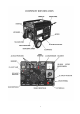
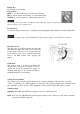
Engine Key To start and stop the engine: Key position: OFF: To stop the engine. Key can be removed / inserted. ON: To run the engine after starting, or to pull start the unit. START: To start the engine by operating the starter motor. Do not turn the key switch to START position when the engine is running to prevent damage to the starting motor. Recoil Starter To start the engine, turn the key to on, pull the starter grip lightly until resistance is felt, then pull briskly.
ONLY change the Voltage Selector Switch after turning the AC circuit breaker to OFF. The generator may be damaged if the Voltage Selector Switch is changed with the breaker in the ON position. Ground Terminal The generator ground terminal is connected to the frame of the generator, the metal non-current-carrying parts of the generator, and the ground terminals of each receptacle. DC Receptacle The DC receptacle may ONLY be used for charging 12 volt automotive type batteries.
WATTAGE REFERENCE CHART Electric equipment, especially engines produce strong current when being started. The table below offers references when you connect those installations to generator. Tool or Appliance Rated* (Running) Watts Additional Surge (Starting) Watts Light Bulb-75 watt 75 - Deep Freezer 500 800 Sump Pump 800 1200 Refrigerator/Freezer-18 Cu. Ft.
SPECIFICATIONS Generator Engine Standard Features Dimensions Model DS10000E Frequency 60 HZ Max. AC Output 10000 Watt Rated AC Output 8000 Watt Run Time 8 hour Model DS16HPE Type Air Cooled, OHV, 4-Stroke Displacement 419 cc Output 16.0 HP / 3600 rpm Fuel Unleaded Gasoline Fuel Tank Capacity 8.3 Gallon Decibel <72 dBA Oil Alert Standard Battery 12V 18A/hr.
ASSEMBLY Wheel Kit Installation 1 Install the axle assembly on the generator. 2 Install the two wheels on the axle shaft using the flange nuts. 3 Install the two stands on the under frame using the flange nuts. Starter Cables Connection 1. Route the starter cable under the tank. 2. Connect the starter cable to the battery positive ( + ) terminal first, then to the negative ( - ) terminal. When disconnecting, disconnect at the battery negative ( - ) terminal first.
• SAE 10W-30 is recommended for general, all-temperature use. Other viscosities shown in the chart may be used when the average temperature in your area is within the indicated range. 1. Remove the oil filler cap and wipe the dipstick clean. 2. Check the oil level by inserting the dipstick into the filler neck without screwing it in. 3. If the level is low, fill to the top of the oil filler neck with the recommended oil. Fuel • • Check the fuel gauge, and refill the tank if the fuel level is low.
STARTING THE ENGINE / STOPPING THE ENGINE Starting the Engine 1. Make sure that the AC circuit breaker is in the OFF position. The generator may be hard to start if a load is connected. 2. Turn the fuel valve lever to the ON position. 3. The choke will need to be closed, pull the choke rod out to the CLOSED position. 4. Connect the battery cables to the generator. 5. Turn the engine switch to the START position and hold it there for 5 seconds or until the engine starts.
potential for electrical shock. • If an appliance begins to operate abnormally, becomes sluggish or stops suddenly, turn it off immediately. Disconnect the appliance, and determine whether the problem is the appliance, or if the rated load capacity of the generator has been exceeded. • Make sure that the electrical rating of the tool or appliance does not exceed that of the generator. • Never exceed the maximum power rating of the generator.
DC Operation The DC terminals may ONLY be used for charging 12 volt automotive type batteries. Connecting the battery cables: 1. Before connecting the battery charging cables to a battery that is installed in a vehicle, disconnect the vehicle ground battery cable from the battery negative (-) terminal. • • Batteries give off explosive gases; keep sparks, flames and cigarettes away. Provide adequate ventilation when charging or using batteries.
5. Reconnect the vehicle ground battery cable to the battery negative (-) terminal. High Altitude Operation At high altitude, the standard carburetor air/fuel mixture will be too rich. Performance will decrease, and fuel consumption will increase. A very rich mixture will also foul the spark plug and cause hard starting. Operation at an altitude that differs from that, at which this engine was certified, for extended periods of time, may increase emissions.
REGULAR SERVICE PERIOD(2) Before each ITEM Performed at every indicated month or use operating hour interval, whichever comes first. Check ○ ● Engine oil Change Check ○ ● Air cleaner Clean Clean ● Sediment cup Clean-Adjust ● Spark plug Replace Clean ● Spark arrester Check-Adjust ● Idle speed Check-Adjust ● Valve clearance ● Combustion Clean chamber Clean ● Fuel tank and filter Check ● Fuel tube First month or 20 Hrs. Every3 months or 50 Hrs. ○ Every6 months or 100 Hrs. Every year or 300 Hrs.
Never run the generator without the air filter. Rapid engine wear will result. 1. Unsnap the air cleaner cover clips, remove the air cleaner cover, and remove the element. 2. Wash the air cleaner element in a solution of household detergent and warm water, then rinse thoroughly, or wash in nonflammable or high flashpoint solvent. Allow the air cleaner element to dry thoroughly. 3. Soak the air cleaner element in clean engine oil and squeeze out the excess oil.
The gap should be: 0.028 0.031 in (0.70 0.80 mm) 6. Check that the spark plug washer is in good condition, and thread the spark plug in by hand to prevent cross-threading. 7. After the spark plug is seated, tighten with a spark plug wrench to compress the washer. If installing a new spark plug, tighten 1/2 turn after the spark plug seats to compress the washer. If reinstalling a used spark plug tighten 1/8 - 1/4 turns after the spark plug seats to compress the washer.
TROUBLESHOOTING Note: Troubleshooting problems may have similar causes and solutions. PROBLEM The engine will not start No electricity at the AC receptacles POSSIBLE CAUSE SOLUTION Is there fuel in the tank? Refill the fuel tank. Is there enough oil in the engine? Add the recommended oil. Is the spark plug in good condition? Readjust gap and dry the spark plug. Replace it if necessary. Is the fuel reaching the carburetor? Clean the fuel sediment cup.
EASY START INSTRUCTION 1. Fill with at least 1 gallon of fresh gas or until gas shows on the gauge. 2. Fill engine case with (10-30w) motor oil until you can see oil reach the top of dipstick threads. Replace oil cap/dipstick, low oil kill switch is now activated. 3. Turn on/off switch to ON position (located on control panel). 4. Turn fuel control valve to ON position. 5. Pull (CHOKE) lever out to the choke on position. Turn Key to Start or pull the Recoil Start 6.
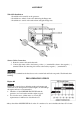
GENERATOR ASSEMBLY AND MOUNTING Generator is supplied with a wheel kit. If you want to install the wheel kit on your unit, please follow the instructions below. If you will not be using the wheel kit, skip this section. 1. Place the bottom of the generator cradle on a flat, even surface. Temporarily place unit on blocks to ease assembly. 2. Secure the support leg to the cradle with cap screws (M8 x 16) and lock nuts (M8) (see figure 22). 3.
CHANGE THE CARBON-BRUSH CHANGE THE AVR 22
R W R Gr Gr R W Autp-throttle R R Gr W CIRCUIT BREAKER 32A Bl W Socket 20A R W R W 30A Socket Socket 30A Bl O R W R Bl Y/G Main coil Y/G Bl Bl Y/G Y/G Br O R coil 2 LB LB LB LB Block 8A LED R O R O G FS Bu Y/G Bu Y/G Bl ST E IG D IN5408 Gr Br/R 9 LED Excitation coil R R R Bu Bu Bu Bu R 3KΩ Bl Bl/W + R Magnetic field coil Ignition Oil alert unit W Current sensor W Generator block Gr Gray R Red Y/G Yellow/Green W White Engine block Valve
EXPLODED VIEW AND PARTS LIST 24
Item Part Qty Description Item Part Qty Description 1 DJ188F-16121-C 1 Starter comp, recoil 43 DJ190FD-14100-A 1 Carburetor assy. 2 GBT5789-B6-8 3 Flange bolt M6x8 44 DJ188F-14003-B 1 Packing, carburetor 3 DJ188F-16120-A 1 Fan, cover comp 45 DJ188FD-14004-A 1 Insulator, carburetor 4 GBT5789-B6-12 13 Flange bolt M6x8 46 GBT6177/10-N-6 2 Flange nut M6 5 DJ188F-11012-A 1 Shroud comp 47 DF6500H-14205-A 1 Stay, air cleaner 6 DJ168F-11039-A 3 Clip.
86 GBT16674-B8-40 7 Flange bolt M8x40 97 DJ190F-12002-A 1 Pin, piston 87 DJ188FD-11001-B 1 Crankcase cover 98 DJ190F-12200-B 1 Connecting rod assy. 88 GBT818-S5-10 3 Flange bolt M5x10 99 DJ188FD-15200-A 1 Control assy. 89 DF3800H-11032-A 1 Fan cover 100 DJ188F-15007-A 1 Spring, governor 90 DJ188F-11007-A 1 Cap assy.
Item Part Qt y Description Item Part Qty Description 106 DF9000H33120 1 Stator Assy. 148 1DF2500H-14302-A 1 Fuel Cock 107 DF9000H-33129 1 Stator cover 149 XP10000E-14405-A 1 Muffler 108 DF3800H33023-A 1 Generator fan 150 DJ188FD-14010-A 1 Gasket Exhaust Pipe 109 GB276-89-6207 1 110 DF9000H-33110-A DF9000H-33104-A-236 111 02 112 DF9000H-33003-A 151 GB5787-1996 2 Flange bolt M8x25 1 Rotor comp 152 DF6500H-31018-I 2 Wheel shaft 1 Stator & Rotor Assy.